8-2 Serial Port Communications and Commands Date Code 20010731
SEL-352-1, -2 Instruction Manual
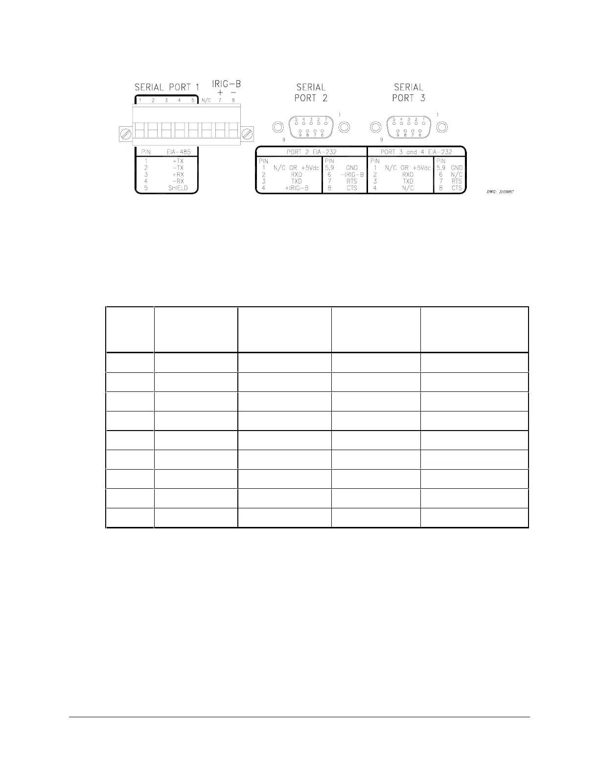
(female chassis connectors as viewed from outside panel)
Figure 8.1: SEL-352 Relay Serial Port Connectors
Pinouts for EIA-232 and EIA-485 ports follow:
Table 8.1: Serial Port Pin Definitions
Pin
Number
Port 1 Rear
EIA-485
Port 2 Rear
EIA-232 with
IRIG-B
Port 3 Rear
EIA-232
Port 4 Front
EIA-232
1 +TX (Out) N/C or +5Vdc* N/C or +5Vdc* N/C
2 –TX (Out) RXD (In) RXD (In) RXD (In)
3 +RX (In) TXD (Out) TXD (Out) TXD (Out)
4 –RX (In) N/C or +IRIG-B* N/C N/C
5 Shield GND GND GND
6 N/C N/C or –IRIG-B* N/C N/C
7 +IRIG-B RTS (Out) RTS (Out) RTS (Out)
8 –IRIG-B CTS (In) CTS (In) CTS (In)
9 NA GND GND GND
* Install a jumper to use the 5 V connection, and remove a solder jumper to disable the IRIG-B
input. See Serial Port Jumpers in Section 2: Installation for more information.
Port 1 is an EIA-485 protocol connection on the rear of the relay. It accepts a plug in/plug out
terminal block that supports wire sizes from 24 AWG up to 12 AWG. The connector is supplied
with the relay. Ports 2, 3, and 4 are EIA-232 protocol connections with Ports 2 and 3 on the rear
of the relay and Port 4 on the front of the relay. These female connectors are 9-pin D-
subminiature connectors. Any combination of these ports or all of them may be used for relay
communication. Table 8.2 gives a list of cables that can be purchased from SEL for various
communication applications.



 To Next Page