Date Code 20010731 Installation 2-31
SEL-352-1, -2 Instruction Manual
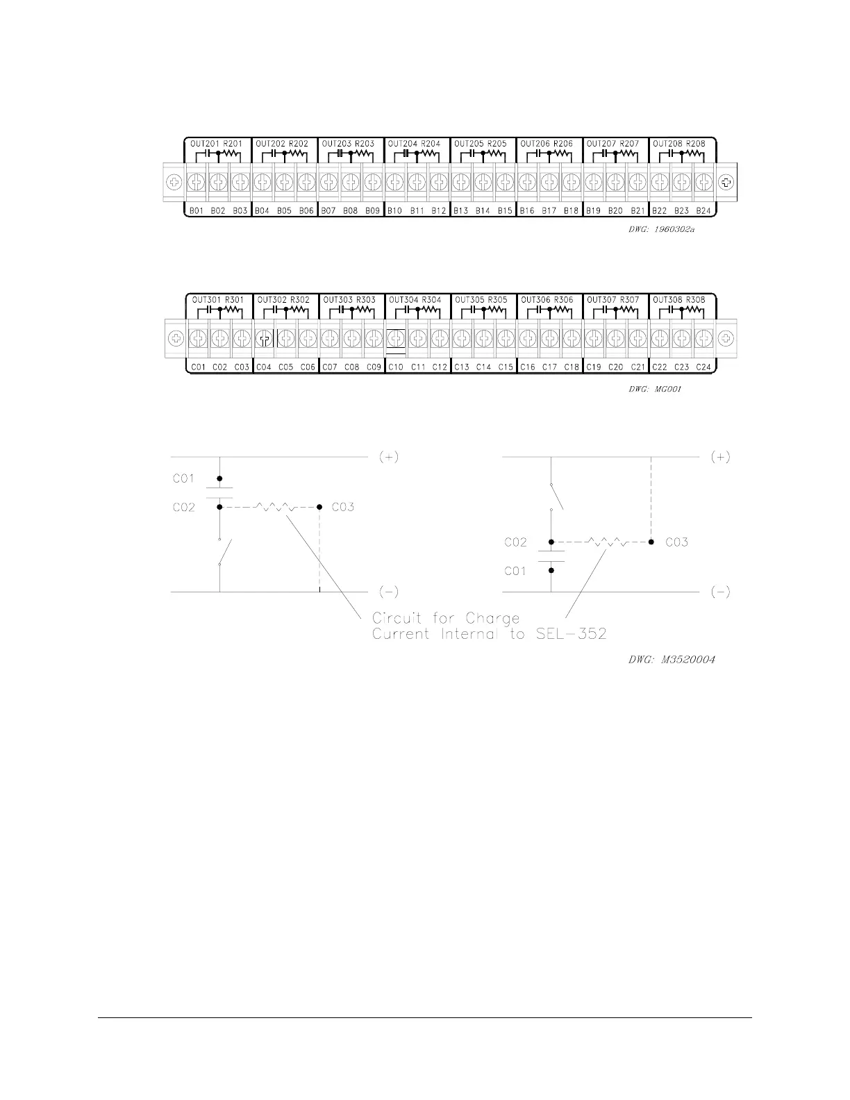
The rear of the relay will be similar to the following drawings:
Figure 2.27: Interface Board 5 Output Contacts (Board Position 1)
Figure 2.28: Interface Board 5 Output Contacts (Board Position 2)
Figure 2.29: Possible Connections for Fast High Current Interrupting Output Contacts
(Circuit Load Not Shown, Third Terminal Connection is Optional)