4-18 Control Logic Date Code 20080110
SEL-387E Instruction Manual
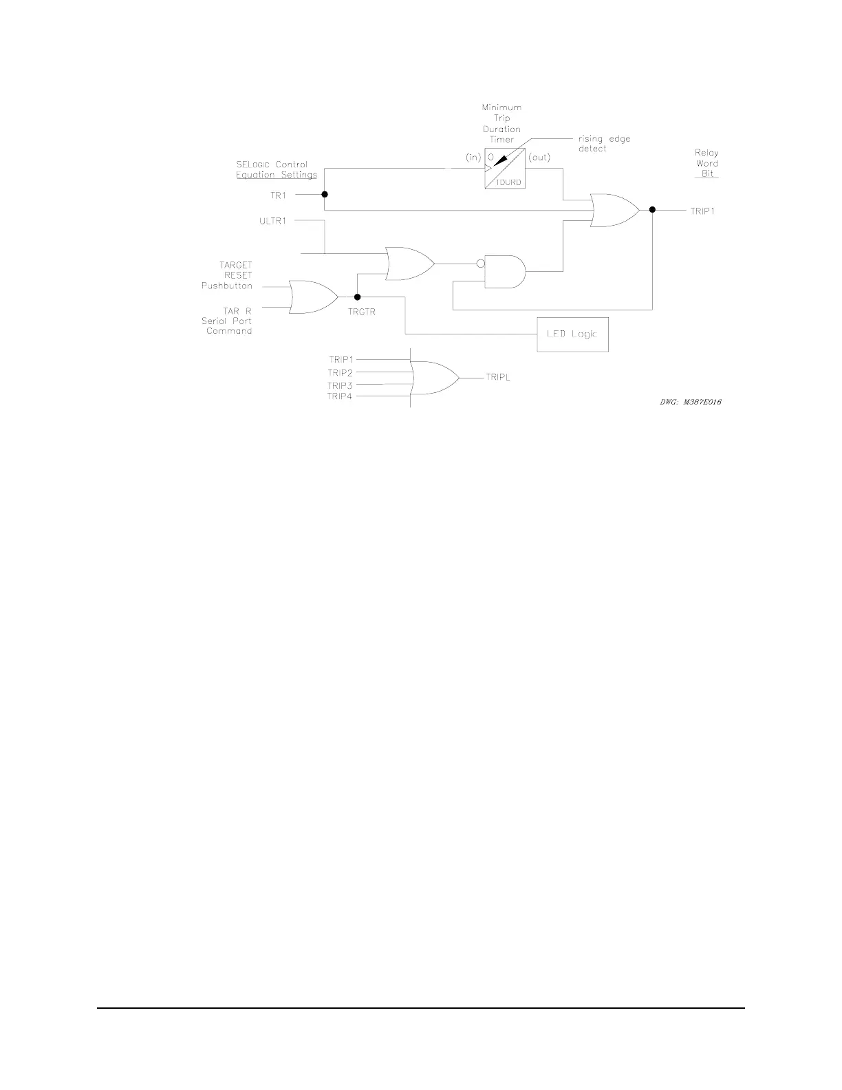
Figure 4.7: SEL-387E Relay Trip Logic (TRIP1)
The logic begins with the assertion of SEL
OGIC
control equation TR1, one of the Group
variables. In our example application Relay Word bits representing three Winding 1 overcurrent
elements and the OPE 1 command are used to assert TR1. TR1 directly asserts TRIP1 via the
three-input OR gate at the right.
However, TR1 may assert more briefly than is needed. There are two means to ensure a longer
TRIP1 assertion. At the top of the diagram is an Edge Trigger Timer. It detects the rising edge
of TR1 and issues a second output to the OR gate. This second output will last the duration of
Group setting TDURD (minimum trip duration timer). Once the rising edge has been detected
and the timing started, the ongoing state of the TR1 input to the timer is ignored. Thus, TRIP1
will be asserted for a minimum of TDURD cycles, even if TR1 is asserted for as little as one
processing interval, or if the unlatch portion of the logic is asserted before TDURD expires. The
default setting of TDURD is nine cycles.
TRIP1 also seals-in itself via the AND gate at the bottom. This AND gate receives the negated
inputs from the unlatching functions. As long as no unlatch function is asserted, the seal of
TRIP1 remains intact. TRIP1 is used to drive an output contact to initiate tripping of the breaker
or breakers. In our example, OUT101 = TRIP1.
There are three means of unlatching the trip logic. The first is the assertion of the SEL
OGIC
control equation setting ULTR1. In our example ULTR1 = !50P13 = NOT 50P13. This current
element is set to pick up at 0.5 A. Thus, ULTR1 asserts when the currents in all three phases
drop below 0.5 A, indicating successful three-pole opening of the breaker.
The other unlatching mechanism is manual, via pushing of the TARGET RESET pushbutton on
the front panel or sending the TAR R serial port command to the relay. Either of these asserts
the Relay Word bit TRGTR, which is also used to reset the LED targets on the front panel. In
the trip logic assertion of ULTR1 or TRGTR places a zero input on the AND gate and thereby
breaks the TRIP1 seal-in loop.