2-18 Installation Date Code 20080110
SEL-387E Instruction Manual
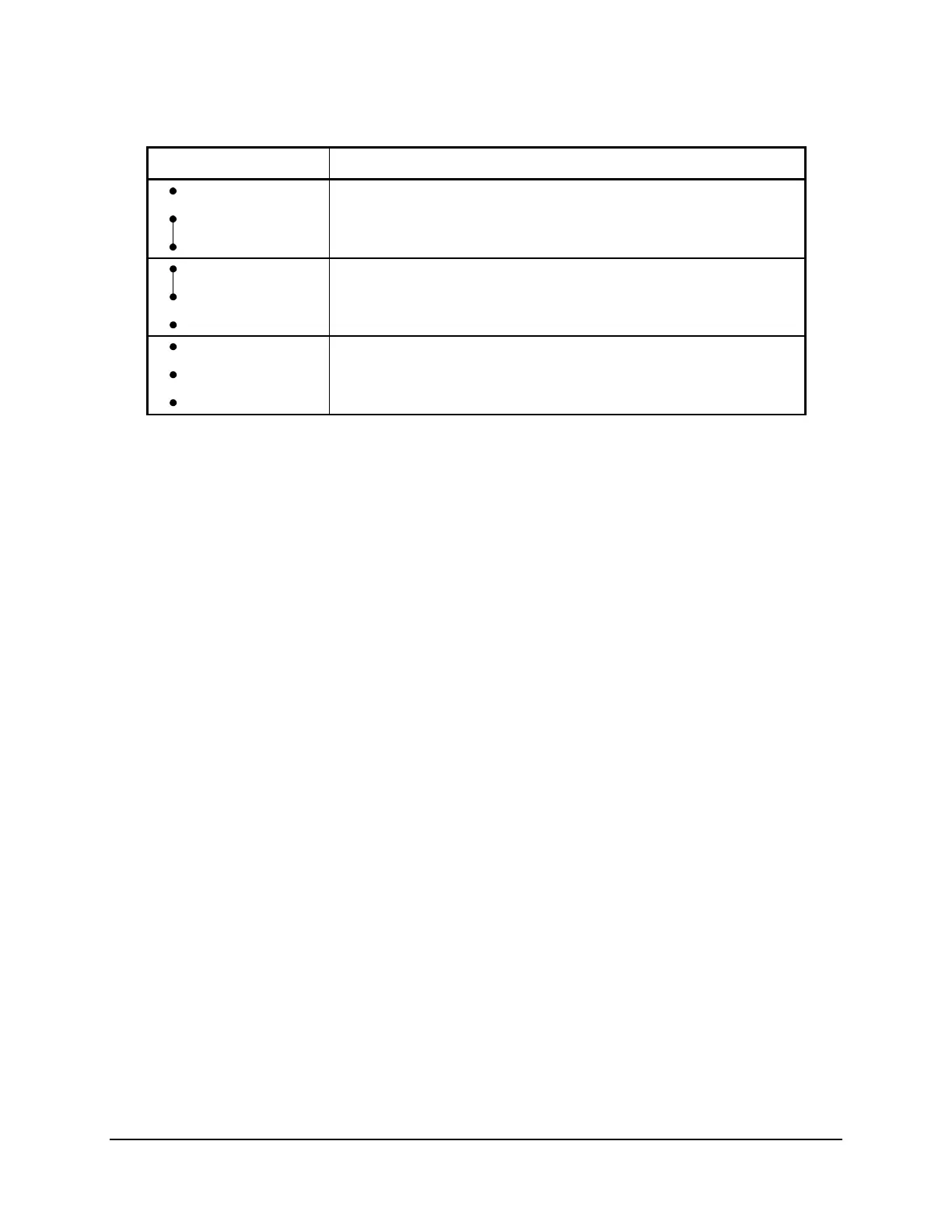
Table 2.2: SEL-387E Relay Second ALARM Contact Jumper Position
JMP23 Position Output Contact OUT107 Operation
Bottom
(Pins 1 & 2)
Second Alarm output contact (operated by alarm logic/circuitry).
Relay Word bit OUT107 has no effect on output contact OUT107
when jumper JMP23 is in this position.
Top
(Pins 2 & 3)
Regular output contact OUT107 (operated by Relay Word bit
OUT107). Jumper JMP23 comes in this position in a standard
relay shipment.
Neither Disable output contact OUT107. If JMP23 is not installed, output
contact OUT107 is not functional and will remain in its
de-energized state.
If jumper JMP23 is installed on the two bottom pins and both output contacts OUT107 and
ALARM are the same output contact type (a or b), they will be in the same state (closed or
open). If jumper JMP23 is installed on the two bottom pins and output contacts OUT107 and
ALARM are different output contact types (one is an “a” and one is a “b”), they will be in
opposite states (one is closed and one is open).
Password and Breaker Jumpers
Refer to
Figure 2.14 and note the password and breaker jumpers identified as JMP6. To change
these jumpers, remove the relay front panel and main board according to the steps outlined
previously in Accessing the Relay Circuit Boards.
Put password jumper JMP6A (left-most jumper) in place to disable serial port and front-panel
password protection. With the jumper removed, password security is enabled. View or set the
passwords with the PASSWORD command (see Section 7: Communications).
Put breaker jumper JMP6B in place to enable the serial port commands OPEN, CLOSE, and
PULSE. The relay ignores these commands while you remove JMP6B. Use these commands
primarily to assert output contacts for circuit breaker control or testing purposes (see Section 7:
Communications).
Do not install jumpers in position JMP6C or JMP6D. If a jumper is in position JMP6D and you
lose dc power to the relay, the relay will power up in SELBoot when power is restored. The
front panel will show “SELBoot” and then a warning to remove the jumper when you attempt
serial port communication.
EIA-232 Serial Port Jumpers
Refer to
Figure 2.14. Jumpers JMP1 and JMP2 are toward the rear of the main board, near the
rear-panel EIA-232 serial communications ports. These jumpers connect or disconnect +5 Vdc
to Pin 1 on the EIA-232 serial communications Ports 2 and 3. SEL normally ships relays with
these jumpers removed (out of place) so that the +5 Vdc is not connected to Pin 1 on the
EIA-232 serial communications ports. JMP1 controls the +5 Vdc for Port 3, and JMP2 controls
the +5 Vdc for Port 2 (see Table 7.1 in Section 7: Communications). If these jumpers are