2-16 Installation Date Code 20080110
SEL-387E Instruction Manual
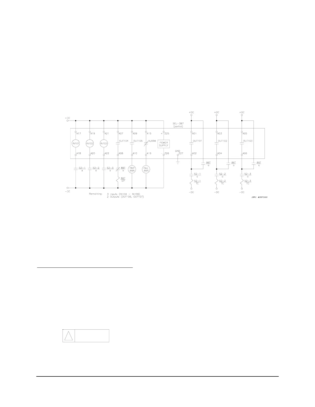
In the dc connection diagram, Figure 2.13, tripping control of the three power circuit breakers is
illustrated. This includes three 52a input contacts to define breaker status (open or closed) and a
separate 86 lockout relay for group tripping on a differential operation. Individual breaker trips
occur for overcurrent operation.
ALARM and annunciation functions are also shown. ALARM is factory wired as a form b
contact, so that it closes under conditions of complete relay power failure. If breaker closing
control were desired, the Trip Annunciator contact (OUT105) would be one of the three separate
output contacts used for connection to the breaker closing coils. That is, for this case the breaker
trip and close functions together would require all seven standard output contacts.
Figure 2.13: Example DC Connections (basic version)
C
IRCUIT
B
OARD
C
ONFIGURATION
In this section we describe (1) how to remove the relay circuit boards so you can change circuit
board jumpers or replace the clock battery and (2) how to replace the circuit boards in the relay.
Accessing the Relay Circuit Boards
1. De-energize the relay by removing the connections to rear-panel terminals + (Z25) and
– (Z26). Accomplish this easily on Connectorized relays by removing the connector at
rear-panel terminals + (Z25) and – (Z26).
2. Remove any cables connected to serial ports on the front and rear panels.
3. Loosen the six front-panel screws (they remain attached to the front panel) and remove the
relay front panel.
The relay contains devices sensitive to electrostatic discharge (ESD).
When working on the relay with front or top cover removed, work
surfaces and personnel must be properly grounded or equipment
damage may result.
4. Each circuit board corresponds to a row of rear-panel terminal blocks or connectors and is
affixed to a draw-out tray. Identify which draw-out tray needs to be removed. An SEL-387E
1.
CAUTION
!