3-6 Protection Functions Date Code 20080110
SEL-387E Instruction Manual
Blocking
While the restrained differential elements are making decisions, a parallel blocking decision
process occurs regarding the magnitudes of specific harmonics in the IOP quantities.
Common (Cross) or Independent Blocking
Use common or independent blocking elements (87BL1, 87BL2, and 87BL3) to supervise the
restrained differential elements. Common blocking disables all restrained elements if any
blocking element is picked up.
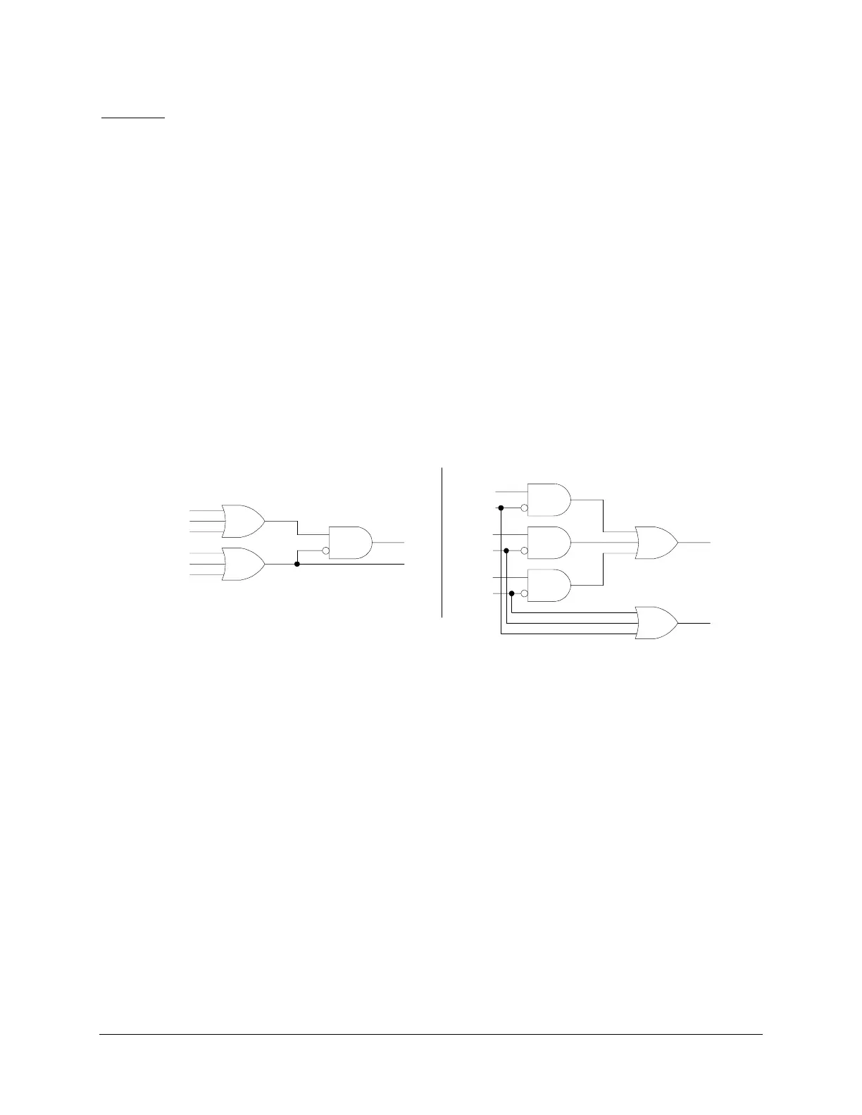
Figure 3.5 shows how independent blocking disables the
restrained element associated with the blocking element.
If IHBL is set to N (No), the logic shown in
Figure 3.5 to the left of the vertical line, IHBL = N,
is enabled. In this case all 87Rn elements enter one OR gate, and all 87BLn elements enter
another OR gate, whose output is negated at the upper AND gate. If the 87Rn OR output asserts
but the 87BLn OR output does not, the 87R Relay Word bit asserts and tripping can take place.
In other words, with IHBL = N, blocking within ANY differential element will prevent operation
and tripping of ALL the restrained differential elements.
(A)
IHBL=N
Common Harmonic Blocking Independent Harmonic Blocking
87R1
87R2
87R3
87BL1
87BL2
87BL3
87R
87BL
(B)
IHBL=Y
DWG: M3871100
87R1
87BL1
87R2
87BL2
87R3
87BL3
87R
87BL
Figure 3.5: Differential Element Harmonic Blocking Logic
If IHBL is set to Y (Yes), the logic shown in
Figure 3.5 to the right of the vertical line, IHBL =
Y, is enabled. Here, the logic pairs 87R1 with negated 87BL1, 87R2 with negated 87BL2, and
87R3 with negated 87BL3 at separate AND gates. In this logic, blocking in a given element will
only disable tripping of that element. In general, this mode of operation might only be used
where three single-phase transformers are used to make up a three-phase bank, and independent-
pole breaker operation is possible, in the harmonic blocking mode. When harmonic restraint is
selected, the relay operates only in the individual blocking mode.
Relay Word bits 87R and 87U are high-speed elements that must trip all breakers. Our example
assigns 87R and 87U to trip variable setting TR4. If either bit asserts, this variable asserts bit
TRIP4, which drives contact OUT104. OUT104 connects to an 86 lockout device, which trips all
breakers via multiple sets of contacts.
Harmonic
Blocking
Figure 3.6 shows how the 87BL1 blocking element will pick up if the second-, fourth-, or fifth-
harmonic operating current, as a percentage of fundamental operating current, is above the 2PCT,