3-8 Protection Functions Date Code 20080110
SEL-387E Instruction Manual
DWG: M3871110
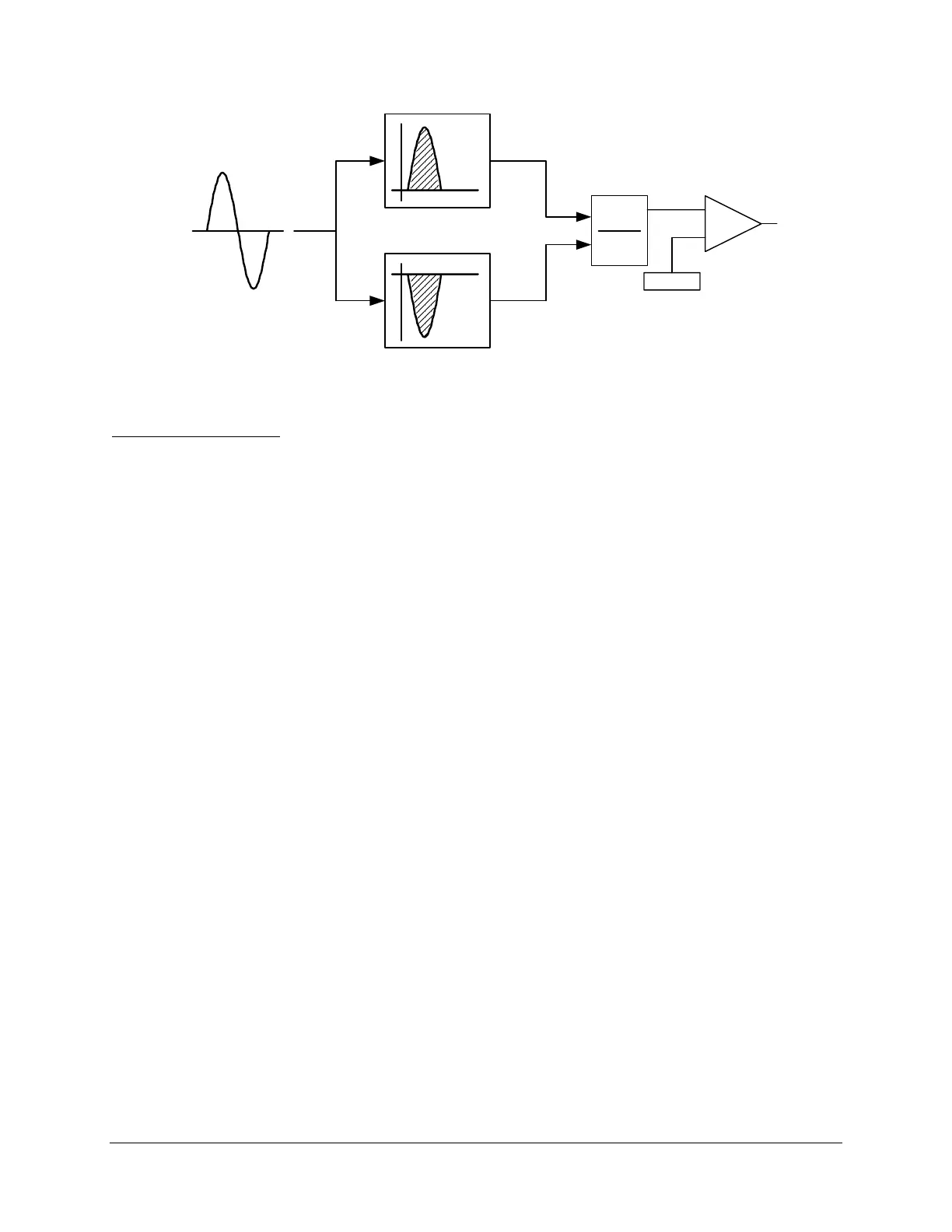
DCBL1
Min
Max
_
+
DCRF
DCR
S
+
S
-
Differential Current
Figure 3.7: DC Blocking (DCBL1) Logic
Setting Descriptions
Differential Element Enable (E87W1 through E87W3)
Range: Y, N, Y1
The SEL-387E Relay has three sets of three-phase current inputs. Depending on the application,
you may not need all of these inputs for the differential zone of protection. You can configure
any unused terminals for stand-alone overcurrent protection. The E87Wn setting specifies which
of the terminals the relay is to include in the differential calculation. An independent setting,
EOCn, exists to enable the overcurrent and demand metering elements. Selecting Y for E87Wn
enables differential element settings for the corresponding winding. Selecting N for E87Wn
disables differential element settings for the corresponding winding; the relay hides the settings,
and they are unavailable for use.
Selecting Y1 makes the fourth-harmonic (PCT4), dc ratio blocking (DCRB), and harmonic
restraint (HRSTR) settings available. This is the only difference between Y and Y1 selection.
CT Connection (W1CT through W3CT)
Range: D, Y
To perform calculations for TAPn values, the relay uses information on whether the CTs are
connected in delta (D) or wye (Y) for each winding. If the CTs are connected in delta, the relay
raises the TAP value by a factor of 1.732.
Also, if the CTs on a particular winding “n” are connected in delta (WnCT = D), then the
secondary currents into the corresponding SEL-387E Relay current inputs (IAWn, IBWn, and
ICWn) are modified before being displayed or used in:
• breaker monitoring (BRE command)
• instantaneous metering (METER command)
• demand metering (METER D and METER P commands)
• through-fault event monitoring (TFE command)