Date Code 20080110 Protection Functions 3-7
SEL-387E Instruction Manual
4PCT, or 5PCT setting threshold, respectively. The blocking element will also pick up if the ratio
of positive and negative dc exceeds a threshold as shown in
Figure 3.7. The blocking prevents
improper tripping during transformer inrush or allowable overexcitation conditions.
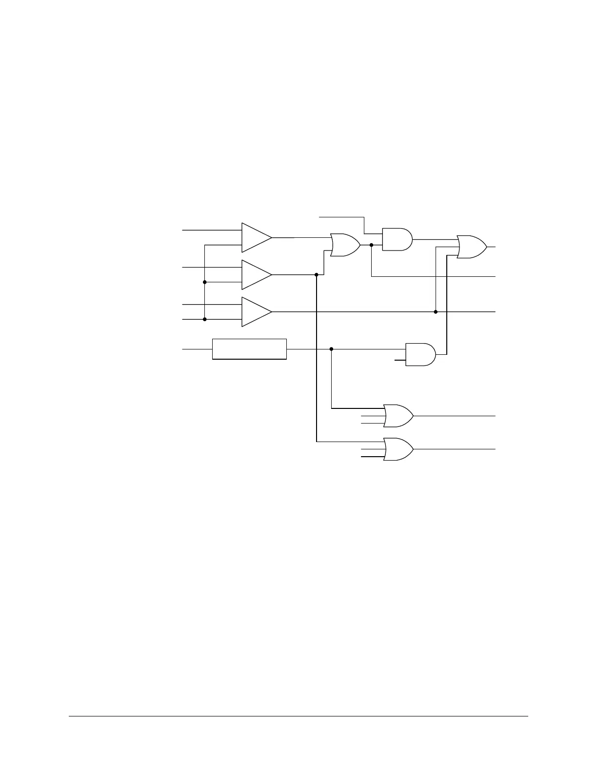
Elements 4HB1, 4HB2, and 4HB3 are combined to form element 4HBL as shown at the bottom
of
Figure 3.6. 4HBL is available as a Relay Word bit but elements 4HB1, 4HB2, and 4HB3 are
not.
An additional alarm function for fifth harmonic, to warn of overexcitation, employs a separate
threshold (TH5P) and an adjustable timer (TH5D). This threshold and timer may be useful for
transformer applications in or near generating stations.
DWG: M3871113
2
nd
Harmonic
Blocking
4
th
Harmonic
Blocking
_
+
I1HB2
I1HB4
I1HB5
IOP1
Differential Current
DCBL1
DC Blocking Logic
_
+
_
+
2HB1
5HB1
87BL1
HRSTR=N
5
th
Harmonic
Blocking
DCRB=Y
DCBL
4HB3
4HB2
4HB1
DCBL3
DCBL2
DCBL1
4HBL
Figure 3.6: Differential Element (87BL1) Blocking Logic
DC Ratio Blocking
Figure 3.7 shows the dc blocking logic for Winding 1. Elements DCBL1, DCBL2, and DCBL3
are combined to form element DCBL as shown at the bottom of
Figure 3.6. DCBL is available as
a Relay Word bit but elements DCBL1, DBL2, and DCBL3 are not.
The dc ratio blocking feature applies to inrush cases with little harmonic content, but a high dc
offset. The measurement principle is that of wave shape recognition, distinguishing between the
time constants for inrush current that typically are longer than the time constants for an internal
fault.