Date Code 20080110 Testing and Troubleshooting 10-23
SEL-387E Instruction Manual
Step 4.
Purpose: Connect and ramp a single-current test source until the appropriate LED
illuminates.
Method: Connect a single-current test source as shown in
Figure 10.6. Turn on the
current test source for the winding under test, and slowly increase the
magnitude of current applied until the 87U element asserts. Note the
magnitude of the current applied. It should equal the value calculated in
step 2, ±5% ±0.02 I
nom
.
Step 5.
Purpose: Repeat the test for each phase for each winding if desired.
Method: Repeat Steps 1 through 4 for each phase. Remember to view the
appropriate TARGET and apply current to the appropriate winding. The
computer terminal will display the LED labels from left to right when the
TAR F
command is issued.
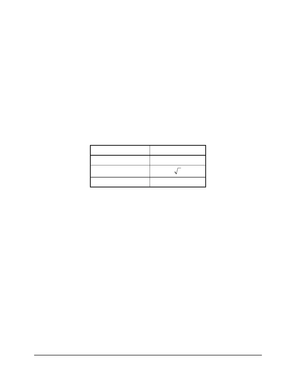
Table 10.3: Connection Compensation Factor
WnCTC Setting A
0 1
Odd: 1, 3, 5, 7, 9, 11
3
Even: 2, 4, 6, 8, 10, 12 1.5
O87P Differential Element Pickup
Step 1.
Purpose: Verify the expected restrained differential element minimum pickup
setting.
Method: Execute the
SHOWSET
command via the relay front panel or serial port
and verify the setting (i.e.,
SHO O87P <Enter>
).
Note:
This value is in
per unit of tap.
Step 2.
Purpose: Calculate the required current to pick up the restrained differential
element.
Method: Calculate the expected pickup for the 87R element by multiplying the
O87P setting by the TAP1, TAP2, or TAP3 setting and the compensation
constant A shown in
Table 10.3. The CT connection compensation
settings W1CTC, W2CTC, and W3CTC determine the A constant for the
calculations. Use the corresponding TAP
n
and W
n
CTC settings for the
winding under test.
Step 3.
Purpose: Display the appropriate Relay Word bit on the front-panel LEDs.
Method: Execute the
TARGET
command (i.e.,
TAR F 87R <Enter>
). The
SEL-387E Relay now displays the state of several differential elements in
the second row of the front-panel LEDs. The 87R bit is the right-most
LED.