10-22 Testing and Troubleshooting Date Code 20080110
SEL-387E Instruction Manual
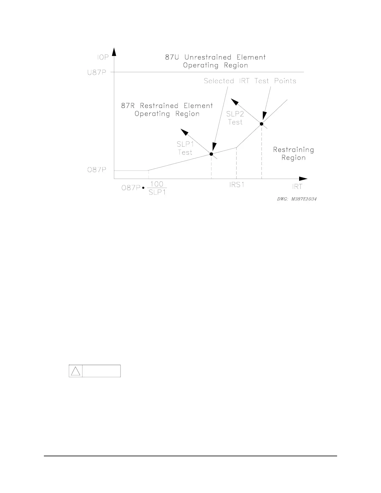
Figure 10.7: Percentage Restraint Differential Characteristic
U87P Unrestrained Differential Element
Step 1.
Purpose: Verify the expected unrestrained differential element pickup setting.
Method: Execute the
SHOWSET
command via the relay front panel or serial port
and verify the setting (i.e.,
SHO U87P <Enter>
).
Note:
This value is in
per unit of tap.
Step 2.
Purpose: Calculate the required current to pick up the unrestrained differential
element.
Method: Calculate the expected pickup for the 87U element by multiplying the
U87P setting by the TAP1, TAP2, or TAP3 setting and the compensation
constant A shown in
Table 10.3. The CT connection compensation
settings W1CTC, W2CTC, and W3CTC determine the A constant for the
calculations. Use the corresponding TAP
n
and W
n
CTC settings for the
winding under test.
CAU TION
!
The continuous rating of the current inputs is 3 • I
nom
. For this
test, you may want to choose low values of U87P and TAP
n
, in
order to limit the required test current to a safe value.
Step 3.
Purpose: Display the appropriate Relay Word bit on the front-panel LEDs.
Method: Execute the
TARGET
command (i.e.,
TAR F 87U <Enter>
). The
SEL-387E Relay now displays the state of several differential elements in
the second row of the front-panel LEDs. The 87U bit is the fourth from
the left.