Date Code 20080110 Protection Functions 3-37
SEL-387E Instruction Manual
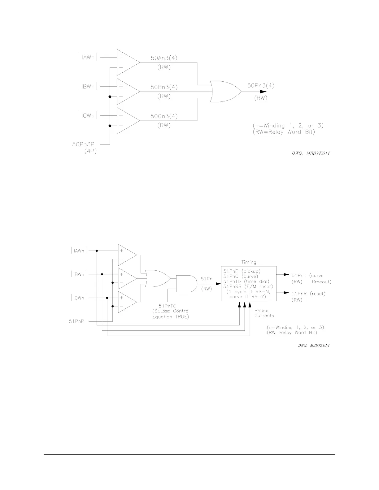
Figure 3.17: 50Pn3 and 50Pn4 Phase Instantaneous O/C Element, Nontorque Controlled
51Pn – Phase Inverse-Time Element
Figure 3.18 shows the logic for the 51P
n
element. The logic compares the magnitudes of phase
input currents IAW
n
, IBW
n
, and ICW
n
to pickup setting 51P
n
P. If one or more current
magnitudes exceed the pickup level, a logical 1 asserts at one input to the AND gate at the center.
The torque-control SEL
OGIC
control equation 51P
n
TC determines the other AND input. If
51P
n
TC is true, Relay Word bit 51P
n
asserts and the inverse curve begins timing.
Figure 3.18: 51Pn Phase Inverse-Time O/C Element, Torque Controlled
Four settings define an inverse-time curve: the pickup setting, 51P
n
P, acts as a horizontal scaling
factor, because the curve formula uses current multiple of pickup as an input; the curve setting,
51P
n
C, defines the particular curve equation, of which there are 10 (five U.S. and five IEC); the
time-dial setting, 51P
n
TD, defines the time dial, which scales the curve in a vertical direction to
vary the output timing for a given multiple of pickup; and the reset setting, 51P
n
RS, defines
whether the curve resets slowly like an electromechanical disk or instantaneously when current
drops below pickup. The phase inverse-time curve looks at all three phase current magnitudes
and times on the basis of the greatest current of the three. It updates this maximum phase current
selection every quarter-cycle.