5-16 Metering and Monitoring Date Code 20080110
SEL-387E Instruction Manual
THRU = 50P23
To block triggering of through-fault events resulting from transformer inrush, consider settings
such as
THRU = 50P23 * !87BL
Note
: The above examples show the designated current inputs (ETHRU = 2) and triggering
element (THRU = 50P23) both from Winding 2. While this is a common setting
approach, triggering elements can be from any winding or be of any element available
in Table 4.8 (e.g., THRU = IN101; set to trigger a through-fault event on the assertion
of input IN101).
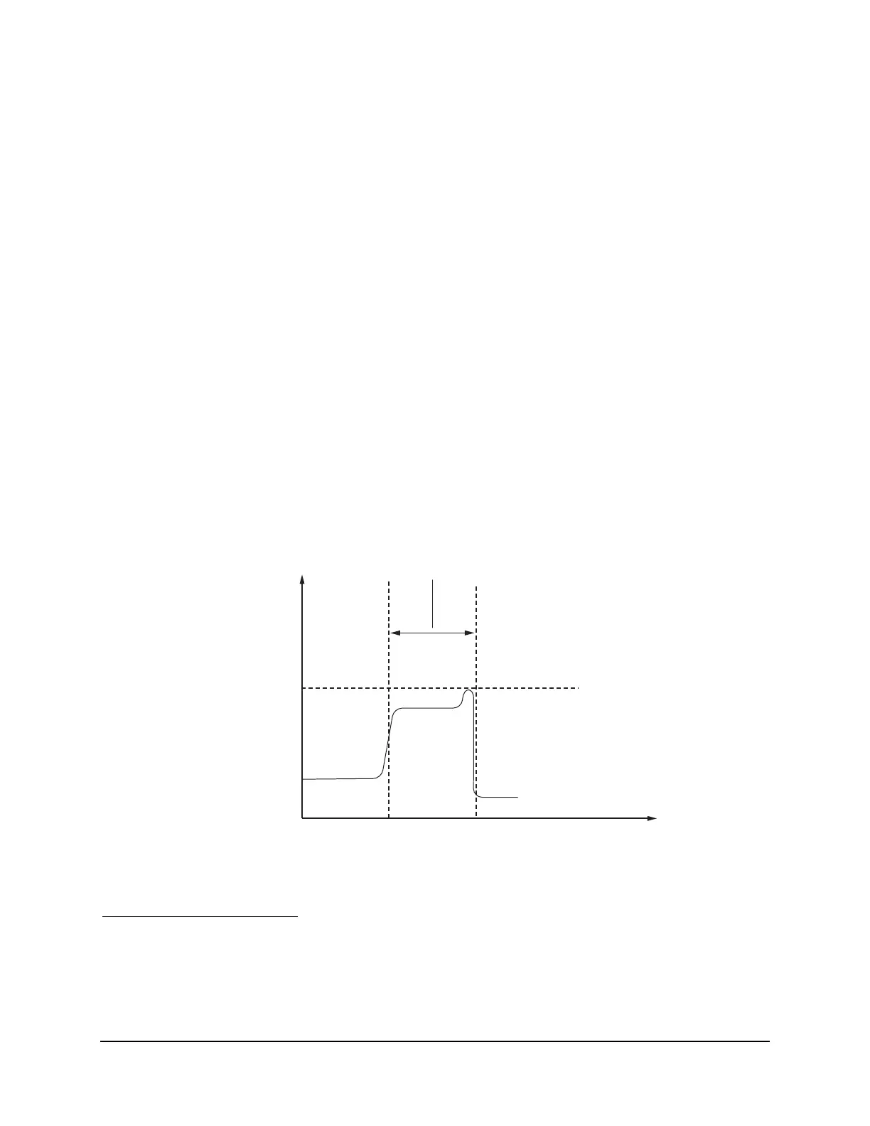
Figure 5.7 shows the time progression of a through fault, such as that in
Figure 5.6. Typically,
SEL
OGIC setting THRU would be set to some instantaneous overcurrent element (e.g., THRU =
50P23). When THRU asserts at the outset of the through fault, event duration timing begins.
When THRU de-asserts (e.g., the distribution feeder breaker interrupts the fault), through-fault
event duration timing ends and the duration time is recorded for that event.
If SEL
OGIC setting THRU is asserted (by whatever means), then maximum currents are recorded
for the monitored current inputs.
Figure 5.7 shows the current jumping up to a short-term
maximum before being interrupted (perhaps the feeder fault “burned through” and became more
“bolted”). This short-term maximum current, which occurred within the duration timing, is what
gets recorded for the particular monitored phase.
Through-fault
event duration
(SEL
OGIC
setting THRU asserted)
trigger
max.
current
I
t
Figure 5.7: Through-Fault Triggering, Duration, and Maximum Currents
Through-Fault Calculation
The through-fault event monitor uses the recorded duration time value and maximum currents to
perform simple I
2
t calculations and cumulatively stores results of these calculations for each
monitored phase. For example, if a through fault is 6000 A primary (maximum) and lasts 0.067
sec., the monitor would calculate I
2
t for that individual event as follows: