Date Code 20080110 Metering and Monitoring 5-17
SEL-387E Instruction Manual
(6 kA)
2
x 0.067 sec. = 2.412 (kA)
2
seconds
If the above calculation were for the example in
Figure 5.7, it would be a conservative
calculation (i.e., the calculation would indicate more I
2
t stress/wear than actually occurred). This
is because the current peaked momentarily.
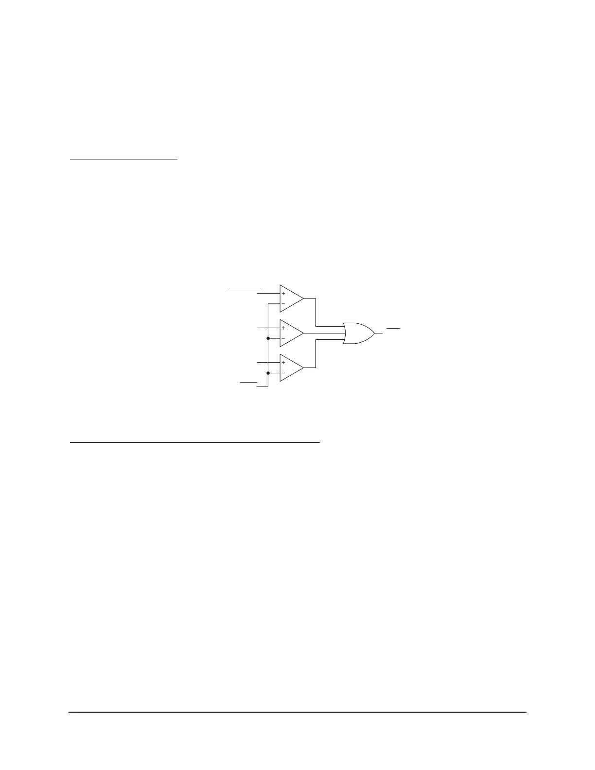
Through-Fault Alarm
Figure 5.8 shows an I
2
t alarm, with Through-Fault I
2
t Alarm Threshold setting ISQT. When the
cumulative I
2
t for any monitored phase exceeds setting threshold ISQT, Relay Word bit ISQTAL
(I-squared-t alarm) asserts. Setting threshold ISQT would usually be set to alarm for excessive,
cumulative transformer bank stress, as such stress corresponds to a certain level of cumulative
I
2
t. Output Relay Word bit ISQTAL can be assigned to an output for annunciation or perhaps
also be used to modify distribution feeder auto-reclosing (e.g., reduce the number of reclosures
from 3 to 2).
ISQTAL
Relay
Word
Bit
Cumulative
Through-Fault
I
2
t Values for:
Setting
A-phase
B-phase
C-phase
Figure 5.8: Cumulative I
2
t Alarm (Relay Word bit ISQTAL)
Through-Fault Event (TFE) Serial Port Command
The
TFE
command displays the following discussed data for each individually recorded
through-fault event:
• Date and time of the through fault
• Duration (seconds) of the through fault
• Maximum current (Amps primary) for each monitored current input
The following cumulative values (updated for each new through-fault event) are also displayed:
• Through-fault count
• Simple I
2
t calculation for each monitored current input