Date Code 20080110 Metering and Monitoring 5-15
SEL-387E Instruction Manual
mechanical stress and the winding insulation to thermal stress. The more feeders on a
distribution bus, the more the transformer bank is exposed to these through faults.
SEL-387
Through-Fault Current
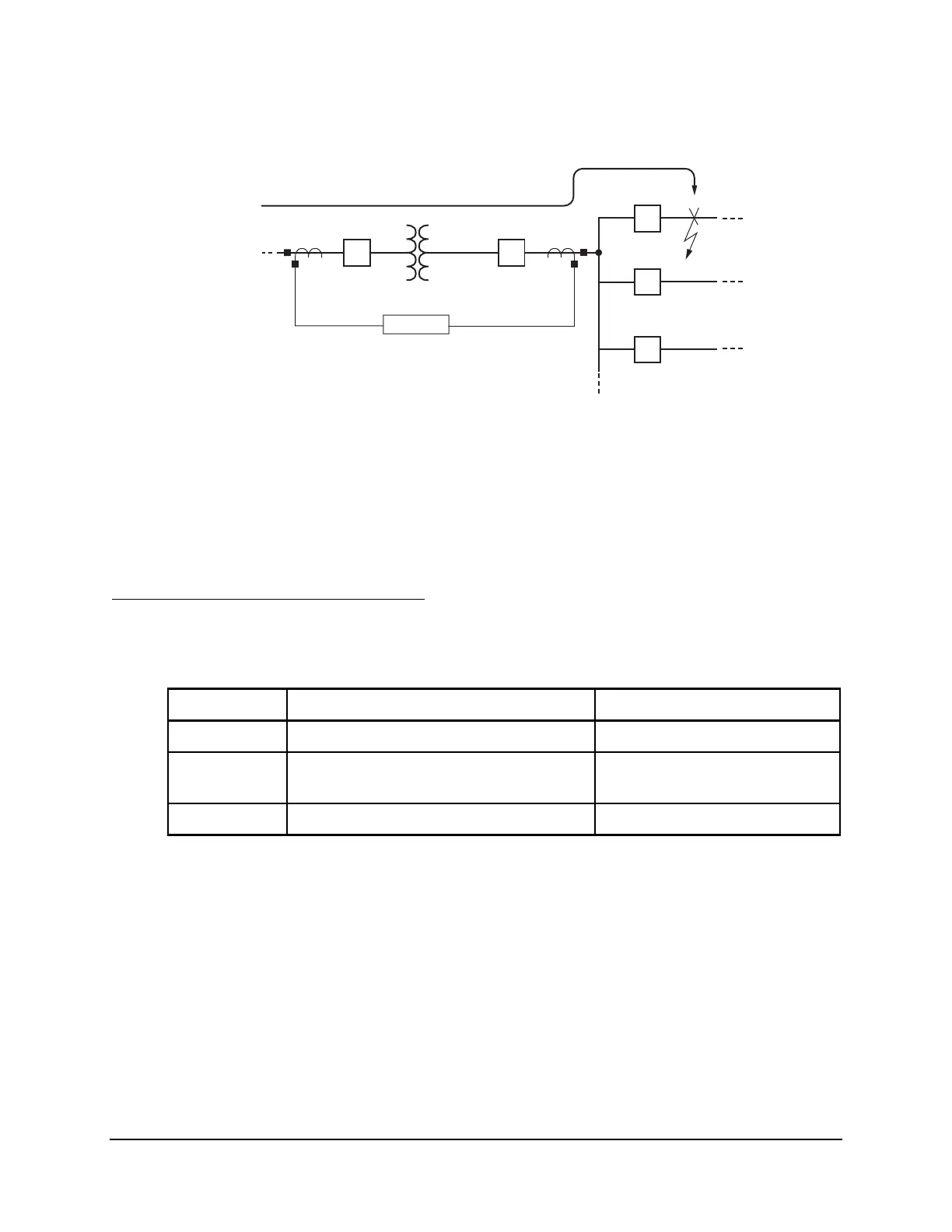
Figure 5.6: Distribution Feeder Faults Expose Transformer Bank to Through Faults
Monitor and document this through-fault activity with the through-fault event monitor in the
SEL-387E Relay. The through-fault event monitor captures maximum current levels, duration,
and date/time for each transformer through fault. The monitor also performs a simple I
2
t
calculation (analogous to the energy expended during the through fault) and cumulatively stores
calculation results for each monitored phase.
Through-Fault Event Monitor Settings
Activate and adjust the through-fault event monitor with the settings in Table 5.2.
Table 5.2: Through-Fault Event Monitor Settings
Setting Definition Range
ETHRU Enable Through-Fault Event Winding N, 1, 2, 3
THRU Through-Fault Event Trigger
(SEL
OGIC control equation
Relay Word bits (Table 4.8)
ISQT Through-Fault I
2
t Alarm Threshold OFF, 0–4294967 (kA)
2
seconds
Setting ETHRU = N turns off the through-fault event monitor. Any other setting selection for
ETHRU designates the winding to monitor for through-fault events. For example, ETHRU = 2
designates Winding 2 as the winding to monitor for through-fault events. Specifically,
Winding 2 current inputs IAW2, IBW2, and ICW2 (A-phase, B-phase, and C-phase,
respectively) are monitored for maximum currents for through-fault events. Changing setting
ETHRU resets/clears through-fault event information (see
TFE C
and
TFE R
command
discussions that follow).
Setting THRU triggers the through-fault event—the through-fault event monitor starts acquiring
maximum current and duration information, along with a date/time tag. Typically, the THRU
setting is set with an overcurrent element. For example, set THRU to trigger a through-fault
event on the pickup of a phase instantaneous overcurrent element on Winding 2: