Date Code 20080110 Protection Functions 3-57
SEL-387E Instruction Manual
27V1P
|V1|
27V1
27PP1
|VPP|
27P2P
27P1P
|VP|
27PP1
Voltage
Magnitude
Calculation
Positive-
Sequence
Voltage
Calculation
PHROT
VA
VB
VC
V1
|VP|
|V1|
|VPP|
(minimum phase
voltage magnitude)
(positive-sequence
voltage magnitude)
(minimum phase-
to phase voltage
magnitude)
DWG: M387E035
Setting
Setting
+
_
+
_
27PP2
+
_
27PP2
TPVI= Y
27P2
27P1
Relay
Word
Bits
DELTA_Y=Y
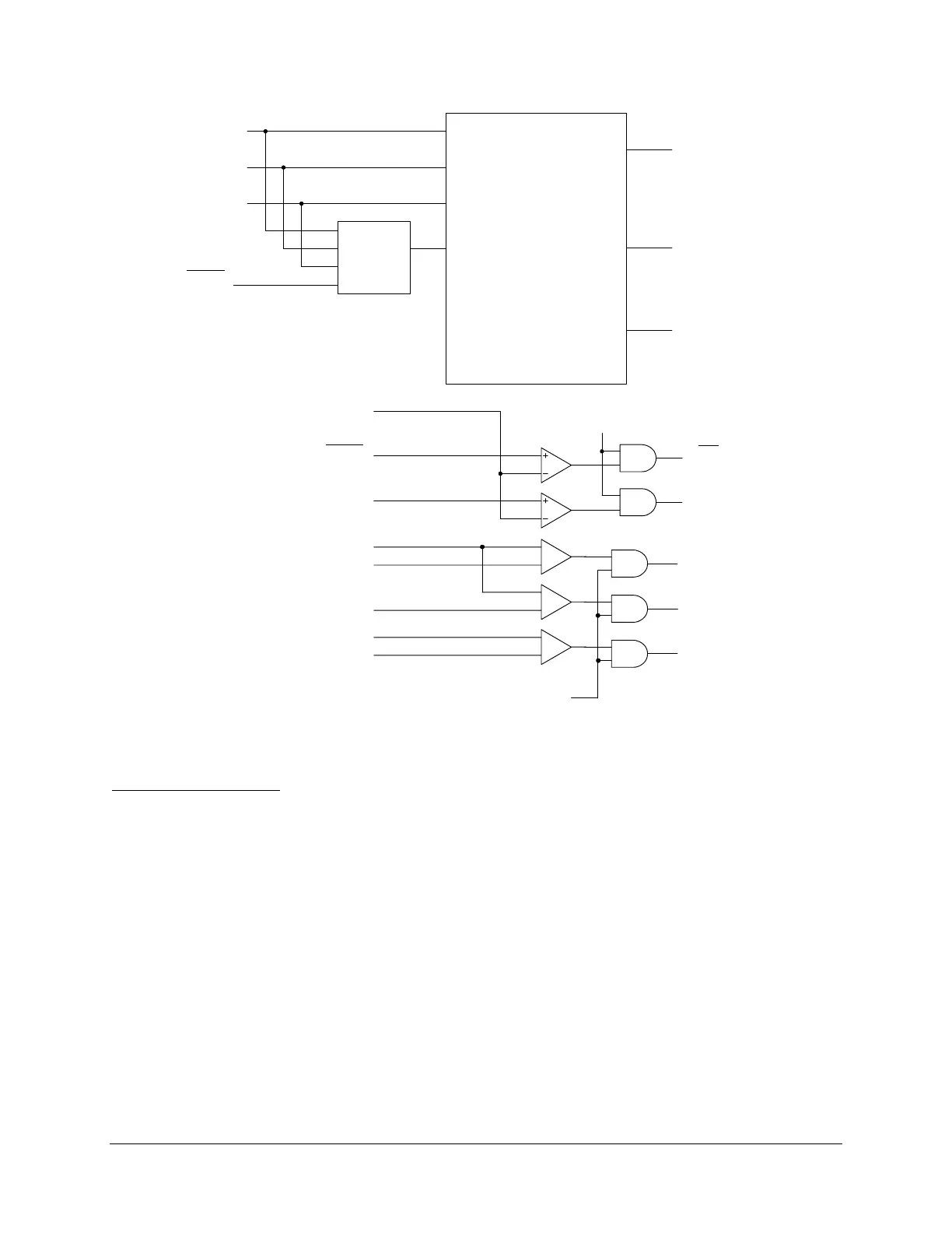
Figure 3.35: Undervoltage Element Logic Diagram
Setting Descriptions
Undervoltage Element Enable (E27)
Range
: Y, N
Set E27 = Y to enable the 27P1, 27P2, 27PP1, 27PP2, and 27V1 undervoltage elements. If you
do not need these elements, set E27 = N. When E27 = N, the relay hides the undervoltage
elements and you do not need to enter the pickup settings. Settings DELTA_Y and TPVI also
affect whether these elements are available.
Overvoltage Element Enable (E59)
Range
: Y, N
Set E59 = Y to enable the 59P1, 59P2, 59G1, 59G2, 59Q, 59V1, 59PP1, and 59PP2 overvoltage
elements. If you do not need any of these elements, set E59 = N. When E59 = N, the relay hides
the overvoltage elements and you do not need to enter the pickup settings. Settings DELTA_Y
and TPVI also affect whether these elements are available.