3-56 Protection Functions Date Code 20080110
SEL-387E Instruction Manual
overvoltage element operates when the maximum phase-to-phase voltage exceeds the set
threshold.
Phase undervoltage elements operate using the minimum of the measured phase voltage
magnitudes, operating if any single-phase measurement falls below the set threshold. The
phase-to-phase undervoltage element operates using the minimum of the measured
phase-to-phase voltages. The positive-sequence (V1) undervoltage element operates when the
measured positive-sequence voltage falls below the set threshold.
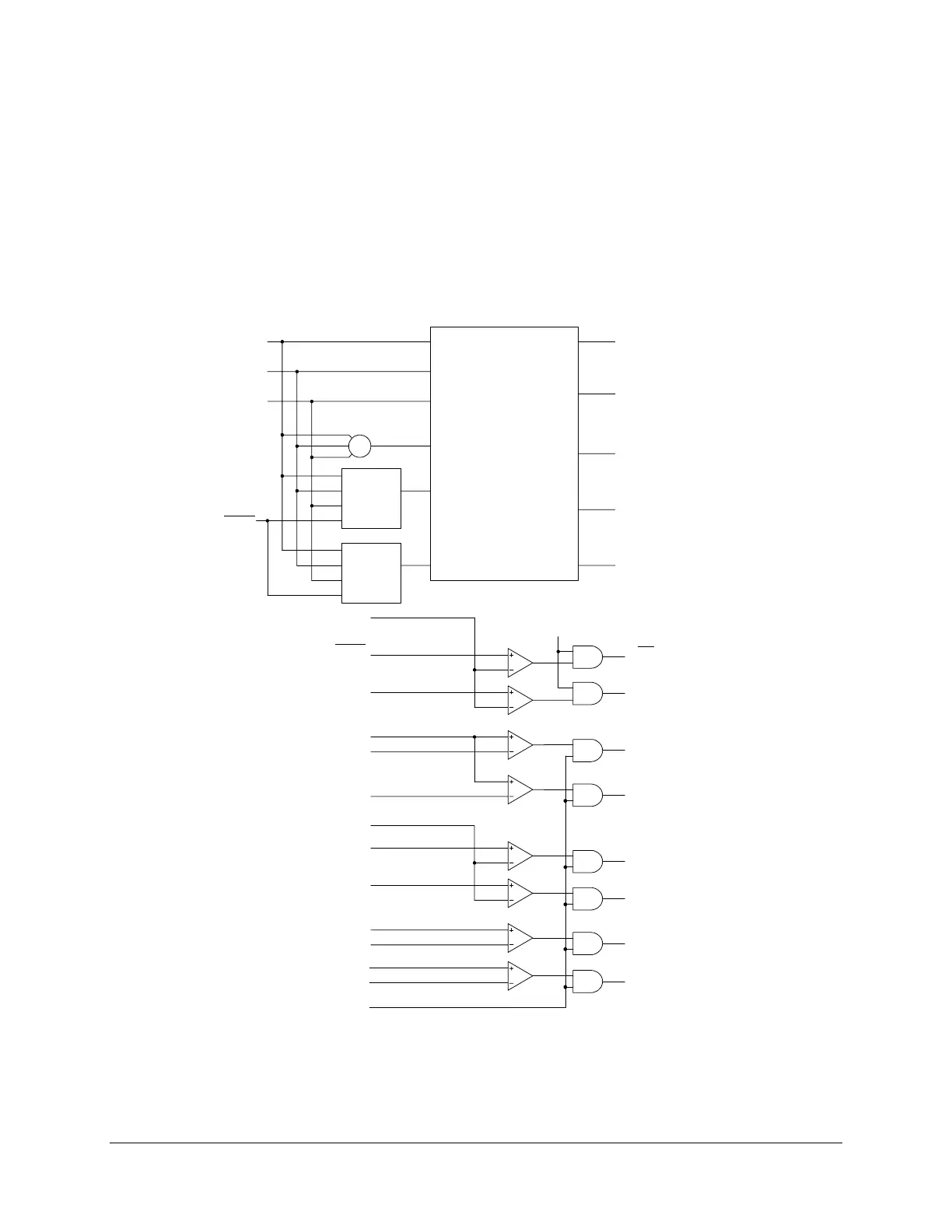
Figure 3.34 and Figure 3.35, respectively, diagram the logic for the overvoltage and undervoltage
elements.
59QP
|V2|
59G2P
59G1P
|VG|=|3V0|
59G2
59G1
59PP1
|VPP|
59P2P
59P1P
|VP|
59PP1
59P2
59P1
Voltage
Magnitude
Calculation
Negative-
Sequence
Voltage
Calculation
Positive-
Sequence
Voltage
Calculation
+
PHROT
VA
VB
VC
VG
V1
V2
|VP|
|VG|
|V1|
|V2|
|VPP|
(maximum phase
voltage magnitude)
(residual voltage
magnitude)
(positive-sequence
voltage magnitude)
(negative-sequence
voltage magnitude)
(maximum phase-
to phase voltage
magnitude)
DWG: M387E034
Setting
Relay
Word
Bits
Setting
59PP2
59PP2
TPVI= Y
DELTA_Y=Y
59Q
|V1|
59V1P
59V1
Figure 3.34: Overvoltage Element Logic Diagram