3-2 Protection Functions Date Code 20080110
SEL-387E Instruction Manual
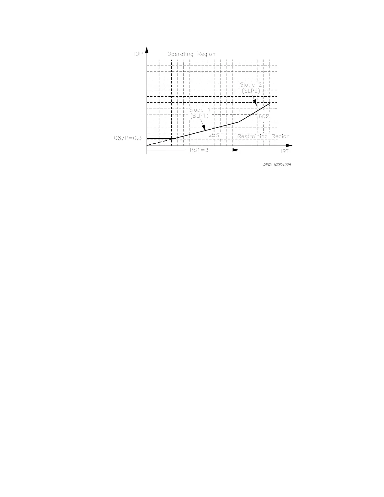
Figure 3.1: Percentage Restraint Differential Characteristic
Figure 3.2, Figure 3.3, and Figure 3.4 illustrate how input currents are acquired and used in the
unrestrained and restrained differential elements. Data acquisition, filtering, tap scaling, and
transformer and CT connection compensation for Winding 1 are shown in
Figure 3.2.
Four digital band-pass filters extract the fundamental, second, fourth, and fifth (not shown)
harmonics of the input currents. A dc filter (not shown) forms one-cycle sums of the positive and
negative values.
Using the transformer MVA rating as a common reference point, TAP scaling converts all
secondary currents entering the relay from the three windings to per-unit values, thus changing
the ampere values into dimensionless multiples of TAP. Throughout the text, the term “TAP”
refers to the per-unit value common to all three windings, whereas “TAPn” refers to the ampere
value of a particular winding(s); TAPmin and TAPmax refer to the least and greatest of the three
TAPn values. This method ensures that, for full-load through-current conditions, all incoming
current multiples of tap sum to 1.0 and all outgoing current multiples of tap sum to –1.0, with a
reference direction into the transformer windings.
Transformer and CT connection compensation adjusts the sets of three-phase currents for the
phase angle and phase interaction effects introduced by the winding connection of the transformer
and CTs. Settings W1CTC through W3CTC determine the mathematical corrections to the three-
phase currents for Winding 1 through Winding 3, respectively. CTC1 is shown in
Figure 3.2 as
the phase angle and sequence quantity adjustment for Winding 1.
I1W1C1, I2W1C1, and I3W1C1 are the fundamental frequency A-phase, B-phase, and C-phase
compensated currents for Winding 1. Similarly, I1W1C2, I2W1C2, and I3W1C2 are the second-
harmonic compensated currents for Winding 1. The dc, fourth-harmonic, and fifth-harmonic
compensated currents use similar names. The I1 compensated currents are used with differential
element 87-1, I2 with element 87-2, and I3 with element 87-3.