Date Code 20080110 Protection Functions 3-29
SEL-387E Instruction Manual
The REF implementation in the SEL-387E Relay uses a directional element (32I) that compares
the direction of an operating current, derived from the line-end CTs, with the polarizing current,
obtained from the neutral CT. A zero-sequence current threshold and positive-sequence restraint
supervise tripping. You can apply REF to a single wye winding in a transformer or to an entire
autotransformer winding with as many as two sets of line-end CT inputs. The neutral CT
connects to one of the three current inputs for Winding 3 (IAW3, IBW3, or ICW3), leaving only
two three-phase winding inputs for normal differential or overcurrent protection purposes.
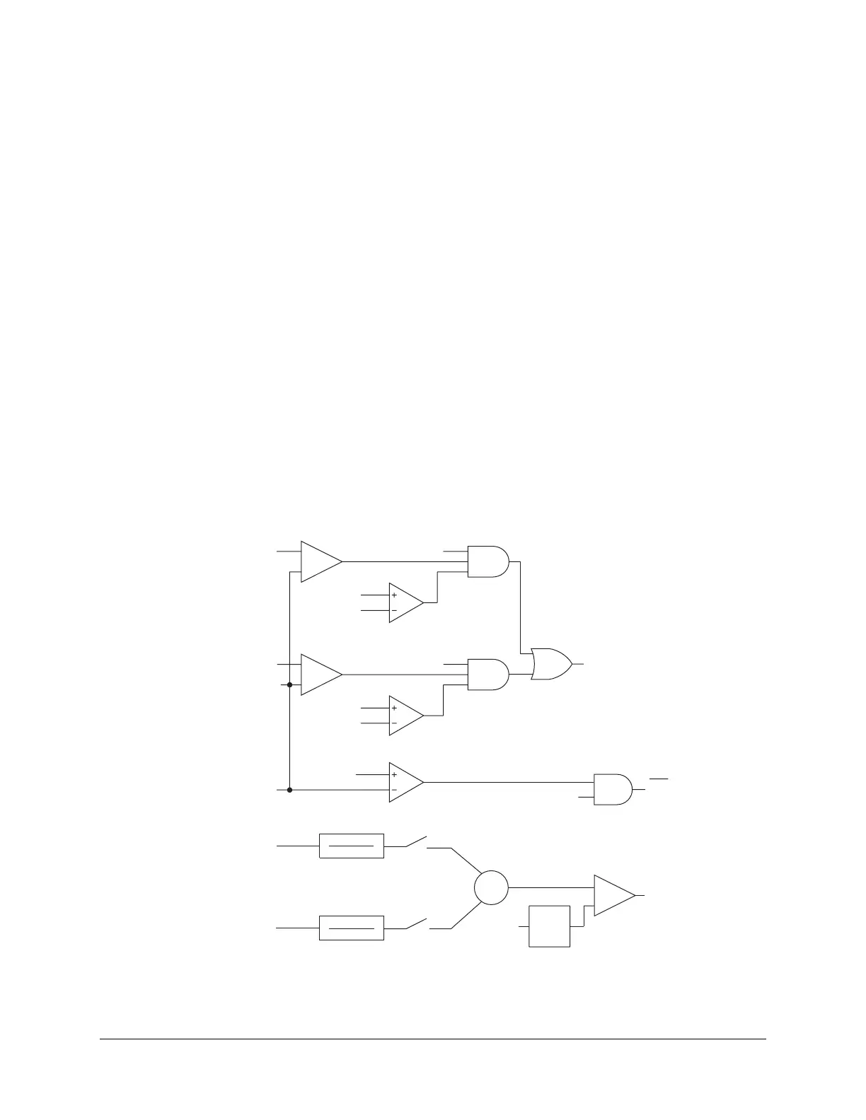
Figure 3.11 shows the REF simplified enable/block logic. The upper logic group determines
whether to enable the REF directional element by assertion of the 32IE Relay Word bit. The two
enabling quantities are assertion of the E32I equation and a magnitude of the neutral CT
secondary current (IRW3) greater than the pickup setting, 50GP. The topmost part of this logic is
a blocking function. This function asserts if any of the winding residual currents used in the REF
function are less than a positive-sequence current restraint factor, a0, times the positive-sequence
current for their respective winding. Such a winding residual current value might occur with
“false Io” or if zero sequence current for that winding exceeds 50GP. False Io can occur in cases
of CT saturation during heavy three-phase faults. If the blocking logic asserts, the CTS Relay
Word bit asserts. To prevent 32IE assertion when CTS asserts, set the E32I setting = !CTS.
The lower logic group adjusts the winding residual currents to a common sensitivity level with
the neutral CT, calculates a phasor sum of the appropriate currents, and compares this sum to the
50GP pickup value. The 0.8 multiplier on the 50GP setting is to ensure that 50GC always asserts
before I2IE. This is to secure the operation of the 32IF element as shown in
Figure 3.12. If the
sum is greater than the pickup level, Relay Word bit 50GC asserts. This bit indicates that the
winding currents are present in sufficient magnitude.
_
+
_
+
50GP
32IOP=1,12,123
32IOP=2,12,123
CTS
I
0W2
50G3 (Relay Word bit)
CTR1
CTR3
CTR2
CTR3
IRW1
IRW2
32IOP=1,12
32IOP=2,12
⏐IRW1⏐
⏐
IRW2
⏐
⏐
IRW3
⏐
⏐⏐
⏐⏐
⏐⏐
⏐
⏐
32IE
E32I
(SEL
OGIC
®
control equation)
_
+
50GC
Relay
Word
Bits
50GP
0.8
∑
a
0
I
1W1
a
0
I
1W2
I
0W1
Figure 3.11: REF Enable/Block Logic