3-42 Protection Functions Date Code 20080110
SEL-387E Instruction Manual
IAW1
∑
Scalar
Multiply
Scalar
Multiply
∑
Scalar
Multiply
Scalar
Multiply
∑
Scalar
Multiply
Scalar
Multiply
∑
Scalar
Multiply
Scalar
Multiply
MAG
MAG
MAG
MAG
MAX
_
+
51PC1P
51PC1
51PC1 Wdg 1 and Wdg 2
Phase Inverse-Time
Overcurrent Element Curve
Timing and Reset Timing
Settings:
51PC1P Pickup
51PC1C Curve Type
51PC1TD Time Dial
51PC1RS E/M Reset? (Y/N)
51PC1T
51PC1R
DWG: M387-5002
_
+
51NC1P
51NC1
51NC1 Wdg 1 and Wdg 2
Residual Inverse-Time
Overcurrent Element Curve
Timing and Reset Timing
Settings:
51NC1P Pickup
51NC1C Curve Type
51NC1TD Time Dial
51NC1RS E/M Reset? (Y/N)
51NC1T
51NC1R
IAW2
IBW1
IBW2
ICW1
ICW2
IRW1
IRW2
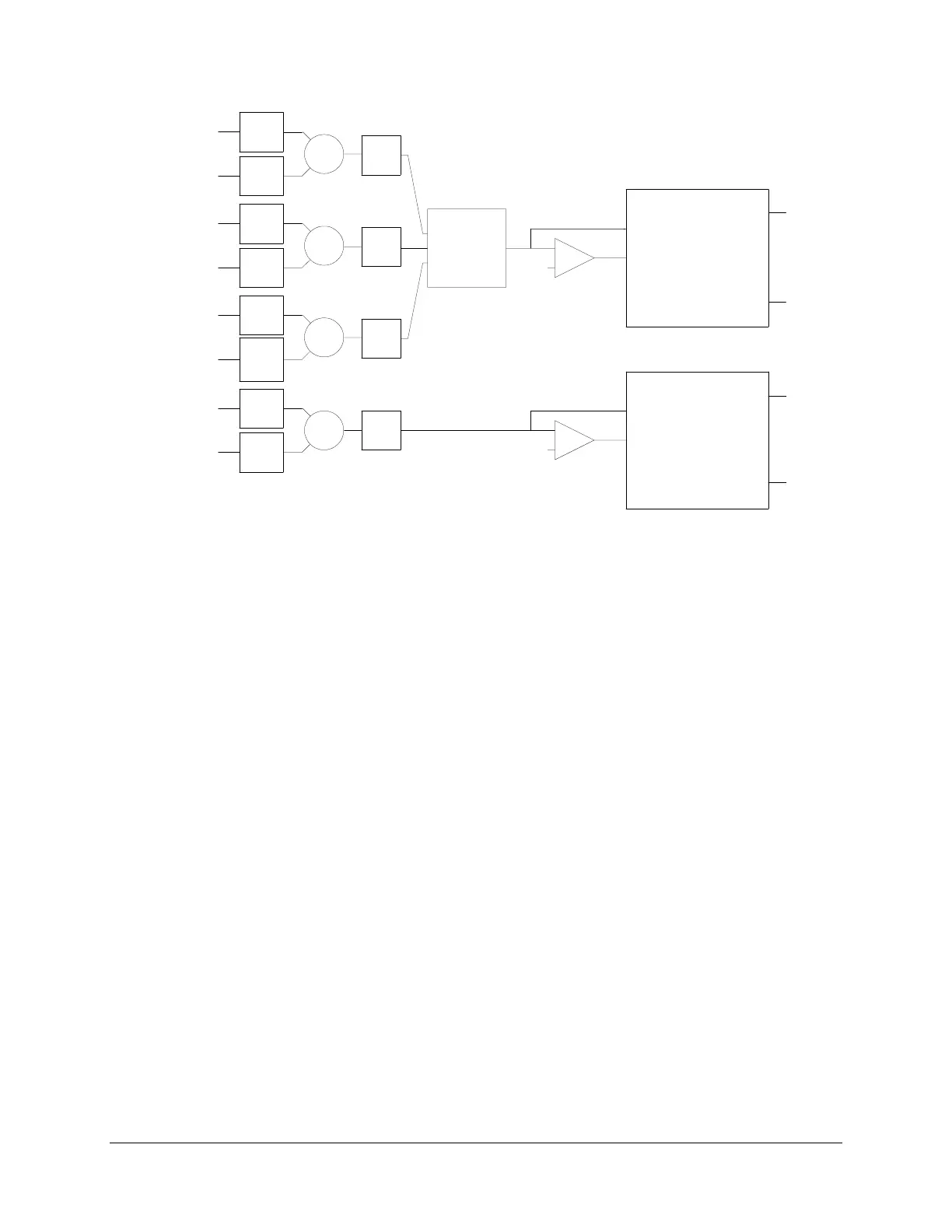
Figure 3.23: 51PC1 and 51NC1 Combined Inverse-Time O/C Elements
The relay determines whether to assert Relay Word bit 51PC1 by selecting the greater of the two
CT ratios, using this ratio as a common base in calculating the combined secondary current, and
then comparing this combined secondary current against the 51PC1P pickup setting. This pickup
setting is a secondary quantity that the relay calculates by dividing the primary current pickup by
the greater of the two CT ratios.
For CTR1<CTR2, the relay performs the following operation on the secondary quantities it
receives from the CTs:
(I
n
W1 • CTR1/CTR2) + I
n
W2,
where
n
= Phase A, Phase B, or Phase C.
The following example illustrates the equivalent operation on the primary quantities entering the
CTs:
Assume
CTR1 = 600/5 = 120
CTR2 = 2000/5 = 400
I
n
W1 = 2000 A (primary)
I
n
W2 = 1000 A (primary)
Pickup = 8000 A (primary)
where
n
= Phase A, Phase B, or Phase C.
Then, converting the observed primary values to secondary values, we have