- 125 -
If Alarm output, Heater burnout alarm output or Loop break alarm output is selected in [Event output
EV allocation], Event output will be turned ON under the alarm active conditions.
Burnout is enabled even in Program control STOP (in Standby) status. However, Event output i
not turned ON.
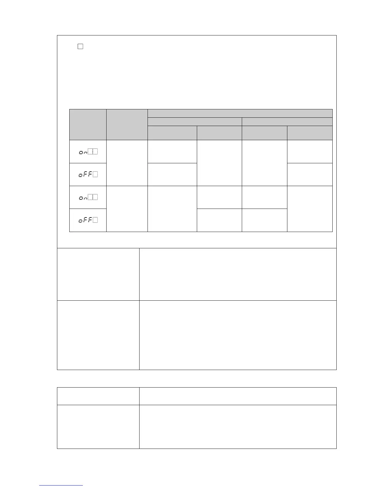
[Output status when input errors occur] can be used only for controllers using direct current and
voltage inputs, and direct current output.
Output status differs depending on selection in [Output status when input errors occur].
Output
status
when input
errors occur
Contents,
Indication
Output Status
OUT1 OUT2
Direct (Cooling)
action
Reverse (Heating)
action
Direct (Cooling)
action
Reverse (Heating)
action
Indicates
[~~~~] and
[er07]
alternately.
ON (20mA) or
OUT1 high limit
value (*)
OFF (4mA) or
OUT1 low limit
value
OFF or
OUT2 low limit
value
ON or
OUT2 high
limit value (*)
OFF (4mA) or
OUT1 low limit
value
OFF or
OUT2 low limit
value
Indicates
[____] and
[er07]
alternately.
OFF (4mA) or
OUT1 low limit
value
ON (20mA) or
OUT1 high limit
value (*)
ON or
OUT2 high
limit value (*)
OFF or
OUT2 low limit
value
OFF (4mA) or
OUT1 low limit
value
OFF or
OUT2 low limit
value
(*) Outputs a value between OFF (4mA) and ON (20mA) or between OUT1 (or OUT2) low limit value and OUT1
(or OUT2) high limit value, depending on deviation.
Warm-up indication
After the power supply to the instrument is turned on, the PV Display
indicates the input type, and SV Display indicates input range high limit
value (for thermocouple, RTD inputs) or scaling high limit value (for
direct current and voltage inputs) for approximately 3 seconds.
Control output is OFF (0 mA for direct current output), and Transmission
output is 0 mA.
Console
communication
By connecting to the tool cable (CMD-001, sold separately) to the tool
cable connector, the following operations can be conducted from an
external computer, using the Console software SWC-PCB101M.
Console communication and Serial communication (C5W, C5 options)
cannot be used together.
(1) Reading and writing of step SV, step time,
PID and various set values
(2) Reading of PV and action status
(3) Function change
Communication line: TTL level
Other
Accessories included Mounting bracket: 1 set
Instruction manual (excerpt): 1 copy
Accessories sold
separately
Terminal cover
CT (Current transformer):
CTL-6-S-H (For Heater burnout alarm output 20 A)
CTL-12-S36-10L1U (For Heater burnout alarm output 100 A)
Tool cable CMD-001