- 127 -
Communication
protocol
Shinko protocol, SV digital transmission, SV digital reception, Modbus
ASCII mode, Modbus RTU mode (Selectable by keypad)
Communication converter IF-400 is available for Shinko protocol and
Modbus protocol.
Data bit/Parity Data bit: 7, 8
Parity: Even, Odd, No parity (Selectable by keypad)
Stop bit: 1, 2 (Selectable by keypad)
Data
format
Protocol
Shinko Protocol
Modbus ASCII Modbus RTU
Start bit
1 1 1
Data bit
7 (8)
Selectable
7 (8)
Selectable
8
Parity
Even (No parity, Odd)
Selectable
Even (No parity, Odd)
Selectable
No parity (Even,
Odd)
Selectable
Stop bit 1 (2)
Selectable
1 (2)
Selectable
1 (2)
Selectable
Response delay time Response from the controller can be delayed after receiving command
from the host computer.
If Response delay time is changed via software communication, the
changed delay time will be reflected from that response data.
• Setting range: 0 to 1000 ms
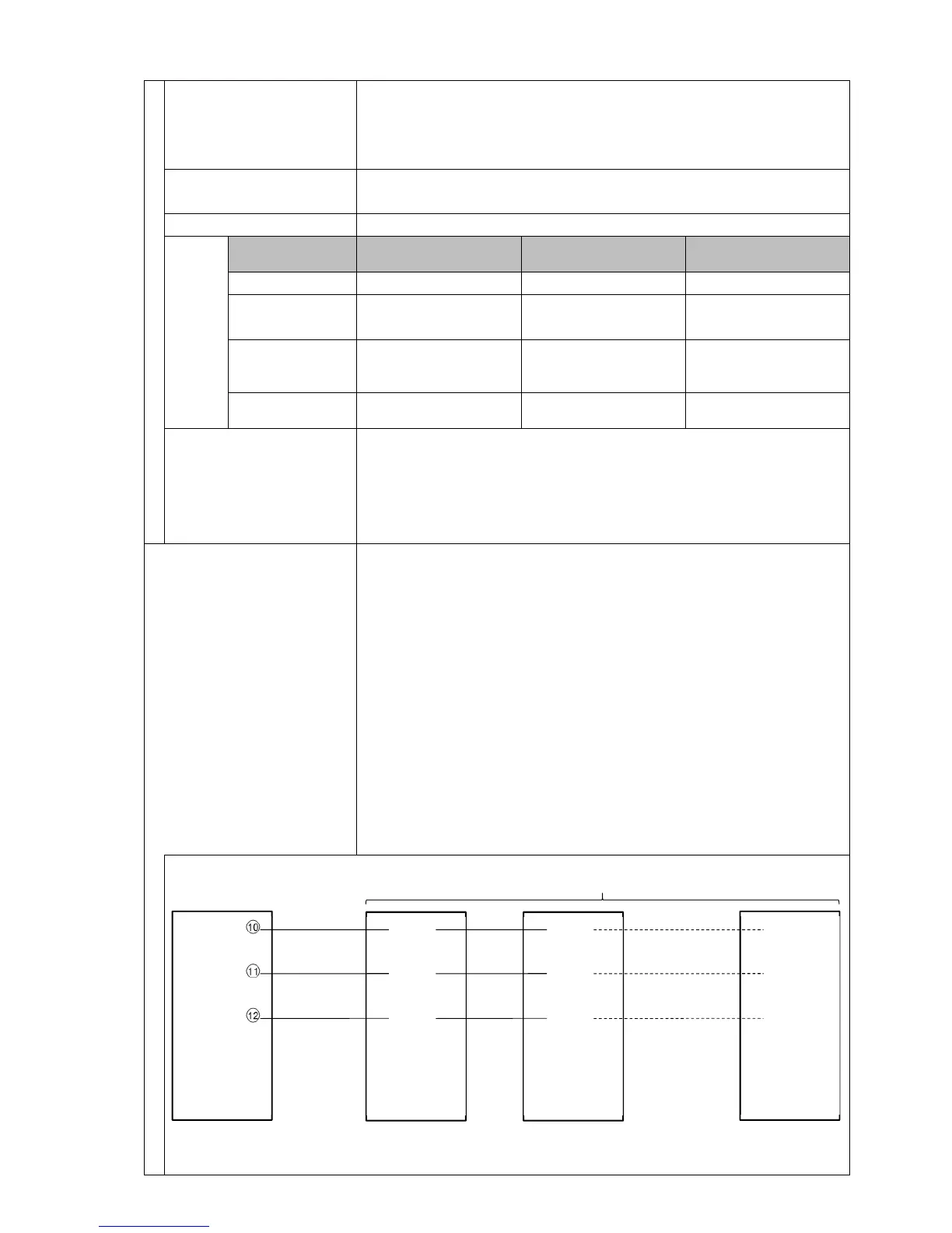
SV digital transmission When ‘SV digital transmission (Shinko protocol)’ is selected in
[Communication protocol], step SV can be digitally transmitted by
connecting to Shinko digital indicating controllers with C5 option (SV
digital transmission).
When ‘SV digital reception (Shinko protocol)’ is selected in
[Communication protocol], step SV can be received via SVTC
command by connecting to Shinko programmable controllers.
Shinko programmable controllers:
• PC-900 with the SVTC (SV digital transmission) option
• PCD-33A with the SVTC (SV digital transmission) option
• PCA1 for which ‘SV digital transmission’ is selected in
Communication protocol]
• PCB1 for which ‘SV digital transmission’ is selected in
[Communication protocol]
(Fig. 11.2-1)
YA(-)
YB(+)
SG
YA(-)
YB(+)
SG
YA(-)
YB(+)
SG
YA(-)
YB(+)
SG
PCB1
Controller with communication function (Max. 31 units)