Factory Default
Setting Item, Function, Setting Range
sok/
/ 1.000
Sensor correction coefficient
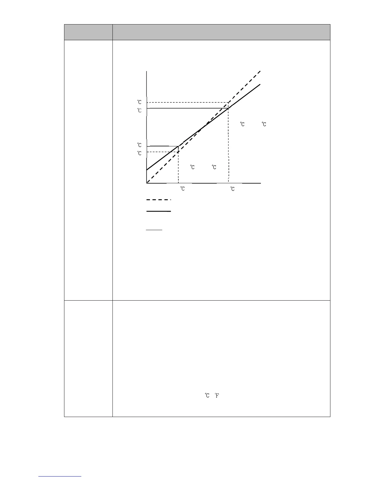
• Sets sensor correction coefficient.
Sets slope of input value from a sensor.
tcoefficiencorrectionSensor
XY
XY' '
(Fig. 8.5-1)
PV after sensor correction= Current PV x (Sensor correction coefficient) +
(Sensor correction value)
Refer to Section ‘9.5 Input Value Correction’ (pp.102, 103).
• Setting range:
-10.000 to 10.000
so//
/ //0.0
Sensor correction
• This corrects the input value from the sensor.
When a sensor cannot be set at the exact location where control is desired, the
sensor-measured temperature may deviate from the temperature in the controlled
location. When using multiple controllers, sometimes the measured temperatures
donotconcur due to differencesin sensor accuracyor dispersionof load capacities.
In such a case, the control can be set at the desired temperature by adjusting the
input value of sensors.
PV after sensor correction= Current PV x (Sensor correction coefficient) +
(Sensor correction value)
Refer to Section ‘9.5 Input Value Correction’ (pp.102, 103).
• Setting range: -1000.0 to 1000.0 ( )
DC voltage, current inputs: -10000 to 10000 (The placement of the decimal
point follows the selection.)
750
700
340
300
300 750
Corrected from
300 to 340 .
Corrected from
750 to 700 .
X
X'
Y'
Y
Slope before correction
Slope after correction