Assembly and Installation
FLOWSIC100 Flare · Operating Instructions · 8013344/11L2/V 2-5/2018-10 · © SICK Engineering GmbH 143
Subject to change without notice
Fig. 72 Analog output module terminal assignment
● Terminal assignment AI module
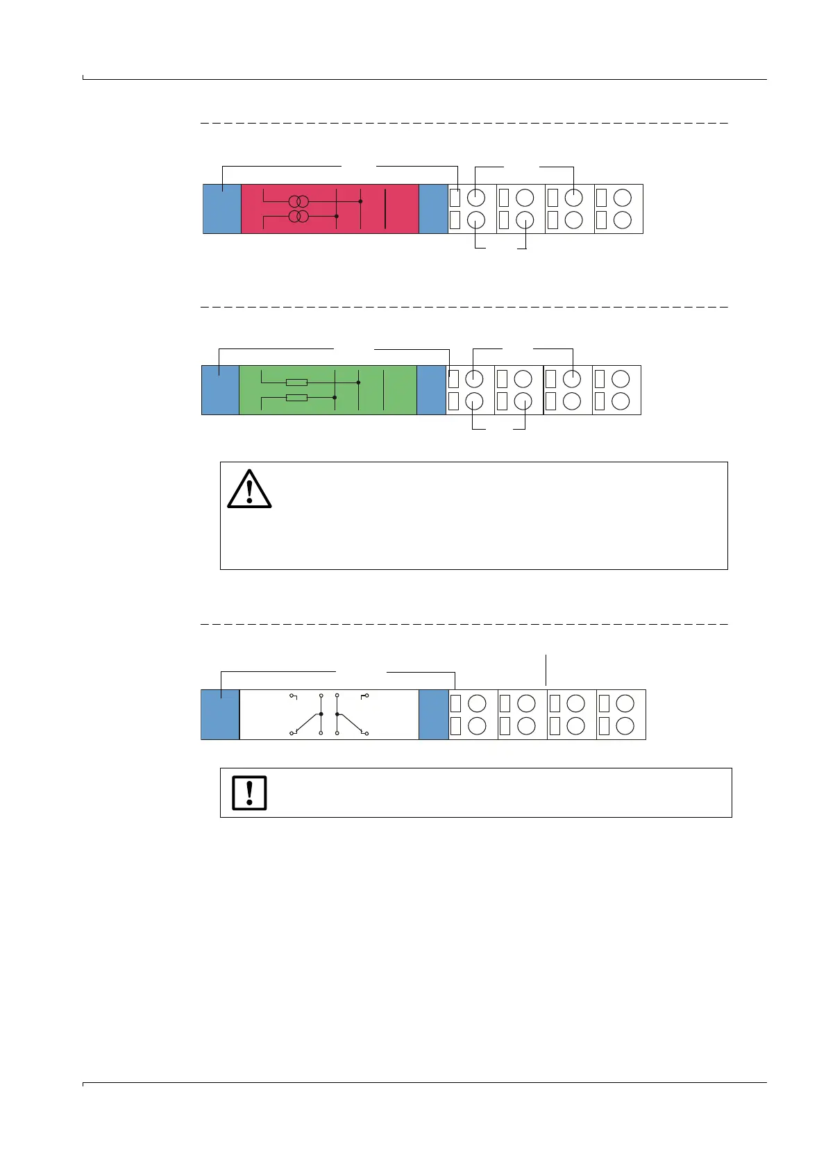
Fig. 73 Analog input module terminal assignment (with external power supply)
● Terminal assignment DO module (2 changeover contacts)
Fig. 74 Digital output module terminal assignment
+
1
AO1
+
2
AO2
Shield
11
12
13
14
21
22
23
24
+-
Analog output module Module carrier
AO 1
+-
AO 2
WARNING:
The analog input module will be damaged if incorrectly connected.
Do not connect the terminals 12, 22, 13, 23 of the analog input module
to GND or earth if the terminals 11, 21 are connected to the internal
supply of the MCUP (delivered configuration) or with another external
supply.
+
1
AI1
11
12
13
14
21
22
23
24
+
2
AI2
Shield
Analog input module Module carrier
+-
AI 2
+-
AI 1
NOTICE:
Screw-fixed terminals for wire sizes 0.5 .. 1.5 mm² (AWG20 ... AWG16).
Digital
Outut
1
2
DO1
DO2
Power
Relay
11
12
13
14
21
22
23
24
n.c.^ com. com. n.c.
DO1 DO2
n.o. com. com. n.o.
Digital output module Module carrier