144 FLOWSIC100 Flare · Operating Instructions · 8013344/11L2/V 2-5/2018-10 · © SICK Engineering GmbH
Assembly and Installation
Subject to change without notice
● Terminal data
n.c.: normal closed
n.o. normal open
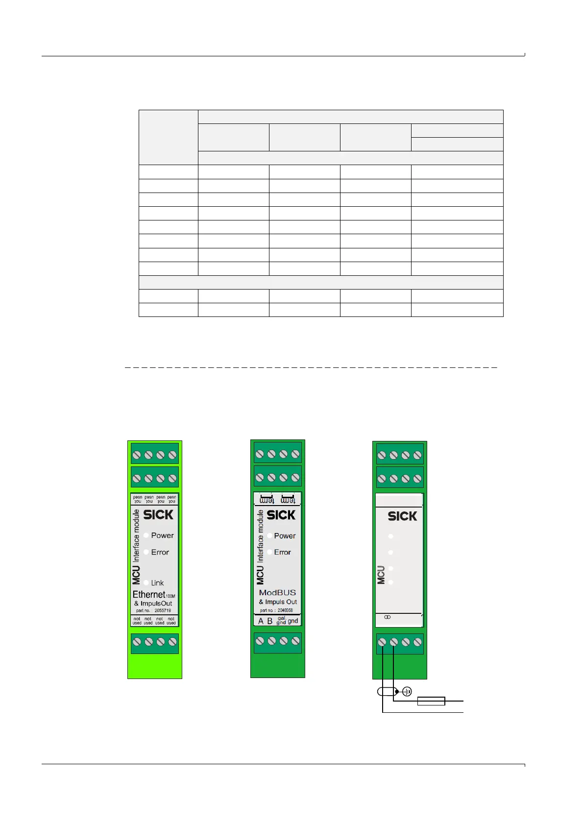
● Terminal assignment interface modules
Fig. 75 Interface module terminal assignment
Terminal Module type
2x Analog
input
2x Analog
output
2x Digital
input
Digital output
2 changeover contacts
Assignment
11 AI 1+ AO 1+ DI 1+ n.c. relay 1
12 AI 1- AO 1- gnd com. relay 1
13 AI 2- AO 2- gnd com. relay 2
14 shield (gnd) shield (gnd) DI 3+ n.c. relay 2
21 AI 2+ AO 2+ DI 2+ n.o. relay 1
22 AI 1- AO 1- gnd com. rel. 1
23 AI 2- AO 2- gnd com. rel. 2
24 shield (gnd) shield (gnd) DI 4+ n.o. relay 2
Rating
max. voltage 3 V d.c. 15 V d.c. 5.5 V d.c. 30 V a.c./d.c.
max. current 22 mA 22 mA 5 mA 2 A
Interface module Interface module Interface module
Ethernet + Impulse Modbus + Impulse HART® Bus
> 250 Ohm
→ PLC input
– +
gnd gnd pulse
– +
gnd gnd pulse
– +
gnd gnd pulse
Tx
Interface module
Power
notnot
usedused
HART
part no. : 2050607part no. : 2050607
& ImpulsOut
gnd
-
+
4..20 mA
MCU
Rx
Impuls
gndgnd
gnd
gal.
 Loading...


