Assembly and Installation
FLOWSIC100 Flare · Operating Instructions · 8013344/11L2/V 2-5/2018-10 · © SICK Engineering GmbH 145
Subject to change without notice
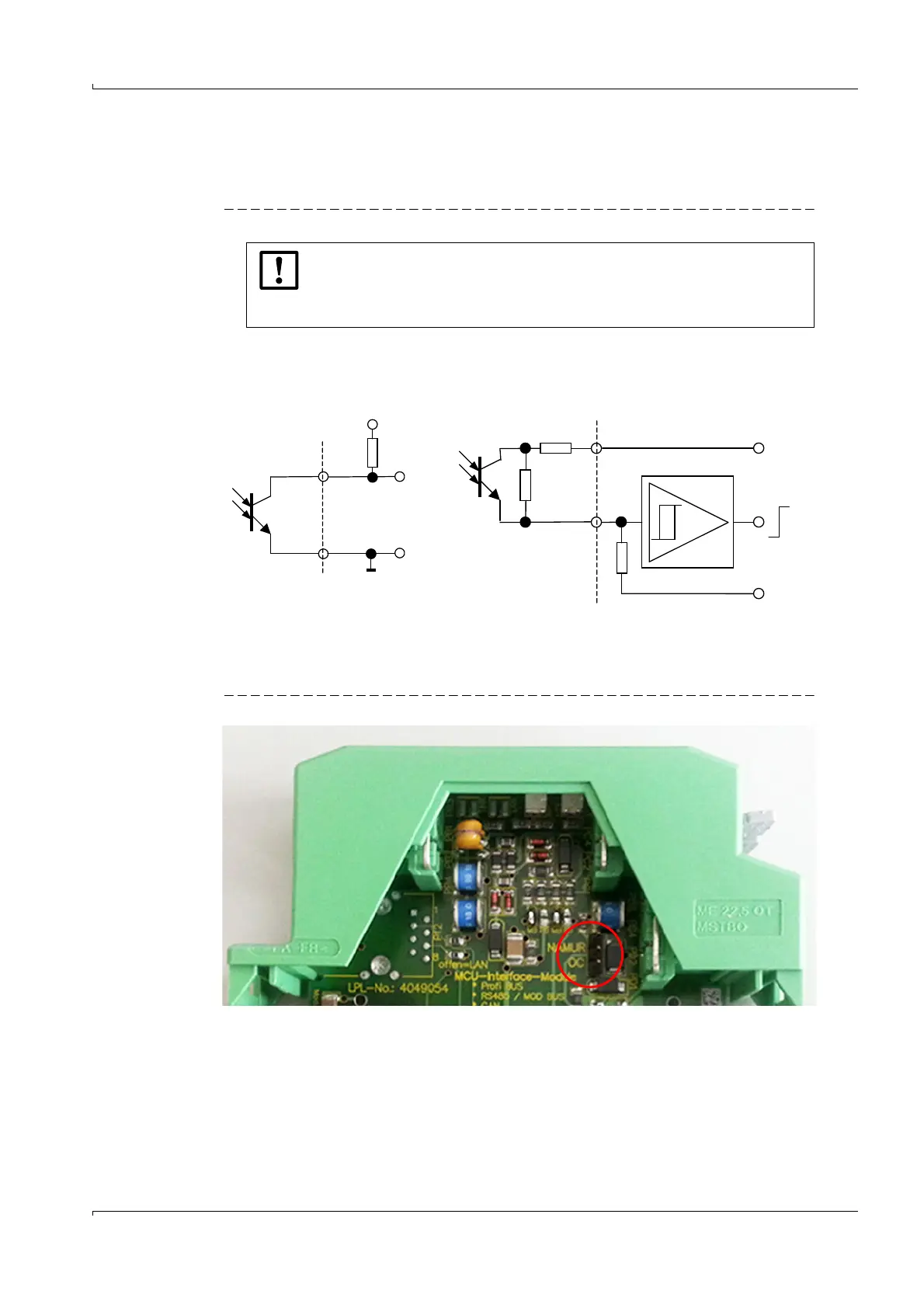
Configuration of impulse output:
By default the interface modules are set to OC. To change the impulse output to NAMUR a
jumper inside the interface module has to be set.
Fig. 76 Impulse output
Figure 77 Interface modules mounted on top-hat rail
NOTICE:
Imax (Open collector connection) may not exceed 100 mA. Otherwise the
impulse output can be destroyed.
Calculate RL according to the equation above.
Open collector (default setting) NAMUR
I
max
= 100 mA
1 k
1 k
10 k
+8.2 V d.c.
0 V
R
L
Vc
Vc 2V–
01A,
---------------------
R
L
Vc 2V–
001A,
---------------------
≤≤