Product Description
FLOWSIC100 Flare · Operating Instructions · 8013344/11L2/V 2-5/2018-10 · © SICK Engineering GmbH 33
Subject to change without notice
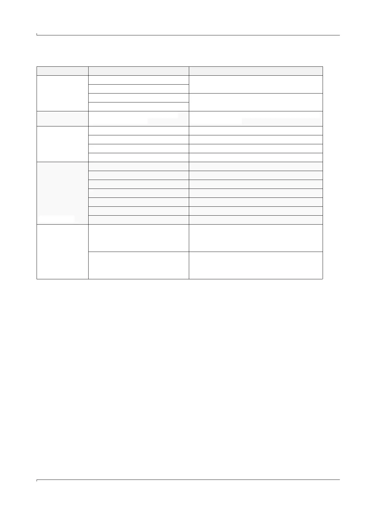
Selection criteria
All sender/receiver units can be used for internal pipe pressure up to max. 16 bar.
If requested by the customer, the sender/receiver units are also available in other versions.
Criteria Design Remark
Gas temperature /
EX certification
Standard version up to max. 180°C
Device certified for gases according to ATEX/IECEx in zone
1 and 2 and CSA Class 1 Division 1/Division 2
High-temperature version up to max. 280°C
Standard version up to max. 180°C
Devices with suitability for gases in zone 2 onlyHigh-temperature version up to max. 260°C
Gas composition
Material for duct probe with transducer:
stainless steel or titanium
Selection according to corrosion resistance with respect to
the measuring medium
Type of installation
Two-sided installation one sender/receiver unit on each of the opposite pipe walls
One-sided installation single sender/receiver unit (probe version)
Installation with nozzle non-retractable sender/receiver units
Installation with nozzle + ball valve retractable sender/receiver units
Pipe diameter
4" ... 24" FLOWSIC100 EX-S, one path
12" ... 24" FLOWSIC100 EX-S, two path
8" ... 72" FLOWSIC100 EX /EX-RE, one path
12" ... 72" FLOWSIC100 EX /EX-RE, two path
12" ... < 48" FLOWSIC100 EX-PR, one path, short version
18" ... < 48" FLOWSIC100 EX-PR, two path, short version
48" ... 72" FLOWSIC100 EX-PR, one path/two path, long version
Flange connection
prepared for mounting on counter flange 2"
CL150 RF acc. to ASME B16.5 or counter
flange DN50 PN16 form B1 acc. to EN
1092-1
FLSE100-EXS, EX and EXRE
prepared for mounting on counter flange 3"
CL150 RF acc. to ASME B16.5 or counter
flange DN80 PN16 form B1 acc. to EN
1092-1
FLSE100-EXPR