Chapter 7 Operating Instructions
M4000 Adv., Adv. A/P, Area
58 © SICK AG • Industrial Safety Systems • Germany • All rights reserved 8010797/PA53/27-06-05
Commissioning
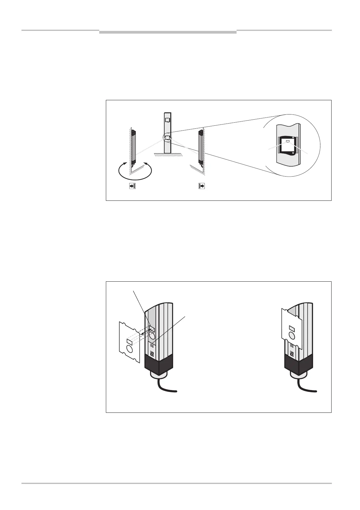
Rotate the receiver until the alignment beam is incident in the centre of the hole in the
alignment template (see Fig. 43). If further mirror columns are used, use the alignment
template for all further mirrors on the mirror columns.
If you do not use an alignment template, the alignment beam must be incident approx.
23.5 mm above the centre of the mirror.
Remove the alignment template from the individual mirror.
Adhere the alignment template for the sender to the beam on the sender that is closest
to the 7@segment display.
The alignment template for the sender is correctly positioned on the sender
(see Fig. 44), when …
– the circular opening is exactly over the beam optics
and
– the tabs on the template are exactly positioned on the edges of the sender housing
and point upward from the 7@segment/LED display.
Align the deflector mirror (depending on the mirror columns, you may need to remove
the cover plate first). With the aid of three adjusting screws, you can finely adjust the
individual mirror (see Fig. 45). The optimal alignment is achieved when the alignment
beam is incident in the middle of the rectangular hole in the alignment template.
Note
Fig. 43: Alignment of the
receiver to the deflector
mirror using the laser
alignment aid
Note
Fig. 44: Attach the alignment
template to the sender
The laser beam is incident in the
middle of the hole in the alignment
template.
edges of the housing
76segment/LED display
AUDIN - 7 bis rue de Tinqueux - 51100 Reims - France - Tel : 03.26.04.20.21 - Fax : 03.26.04.28.20 - Web : http: www.audin.fr - Email : info@audin.fr
 Loading...


