Operating Instructions Chapter 13
M4000 Adv., Adv. A/P, Area
8010797/YT72/2016-02-19 © SICK AG • Industrial Safety Systems • Germany • All rights reserved 115
Subject to change without notice
Technical specifications
Minimum Typical Maximum
Power consumption
M4000 Advanced,
M4000 Area 60/80
0.2 A
Weight, type-dependent See section 13.2 “Table of weights” on page 119ff.
Receiver or M4000 Advanced A/P
Output signal switching devices
(OSSDs)
2 PNP semiconductors, short-circuit protected
18)
,
cross-circuit monitored
Response time
M4000 Advanced,
M4000 Advanced A/P
2 to 6 beams 10 ms
7 to 11 beams 11 ms
12 beams 12 ms
M4000 Area 60/80
Non-coded 11 ms
Coded 17 ms
Additional response time when
using the safe SICK-device
communication (EFI)
+ 4 ms
Switch off time 100 ms
Power-up delay 6.5 × resp. time
Switching voltage
19)
20)
HIGH
(active, U
eff
)
V
S
– 2.25 V 24 V V
S
Switching voltage LOW (inactive) 0 V 0 V 2 V
Switching current 0 mA 500 mA
Leakage current
21)
0.25 mA
Load capacity 2.2 µF
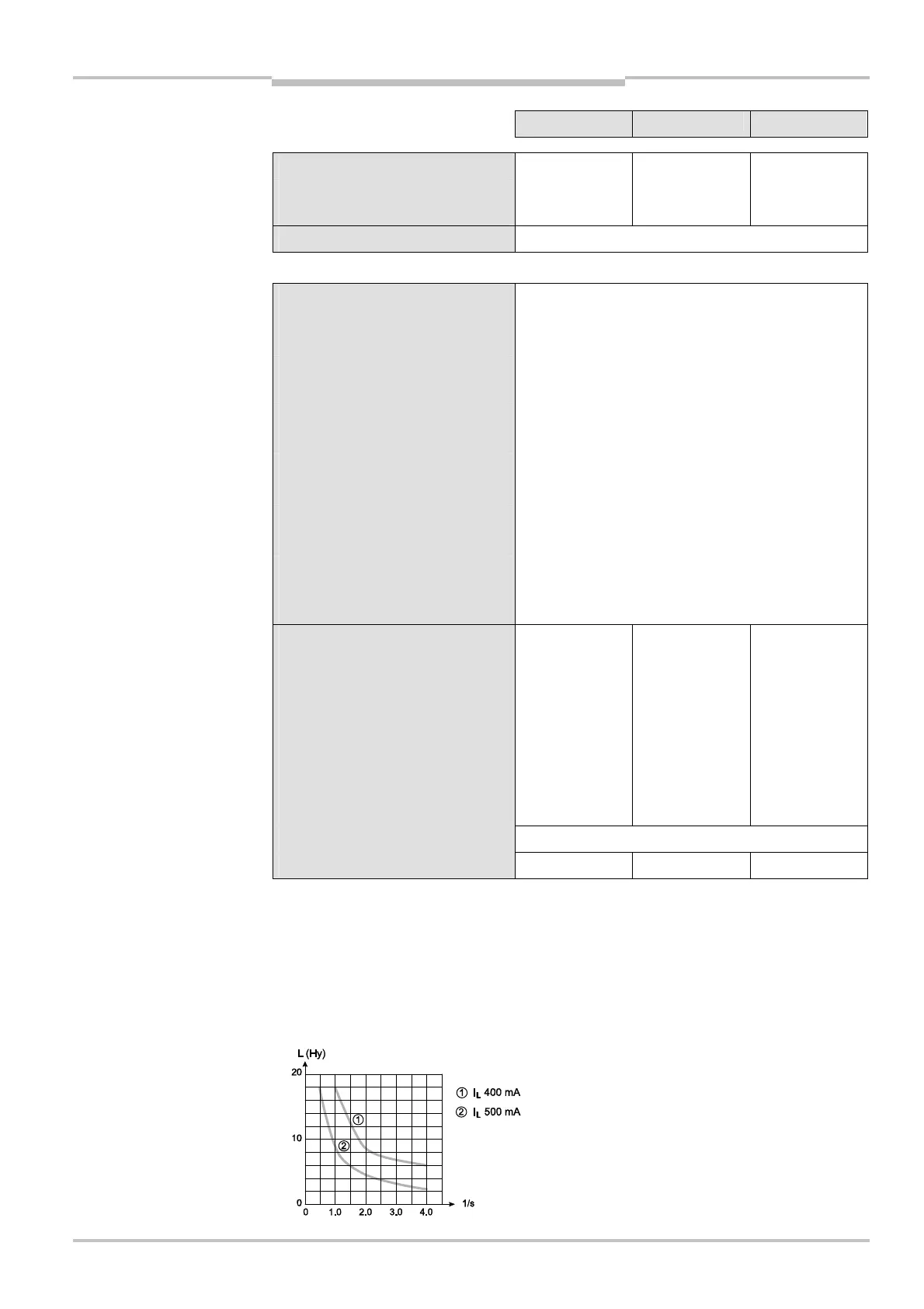
Switching sequence Depending on load inductance
Load inductance
22)
2.2 H
18)
Applies to the voltage range between –30 V and +30 V.
19)
As per IEC 61131-2.
20)
On the device plug.
21)
In the case of a fault (0-V cable open circuit) maximally the leakage current flows in the OSSD cable. The
downstream controller must detect this status as LOW. A FPLC (fail-safe programmable logic controller) must
be able to identify this status.
22)
The maximum rated load inductance is higher with lower switching sequence.