CAUTION
The programs are automatically controlled.
The device no longer measures correctly when a program is interrupted with Start/
Pause/Stop/Continue.
b
Only use these functions when you are sure you can assess the consequences.
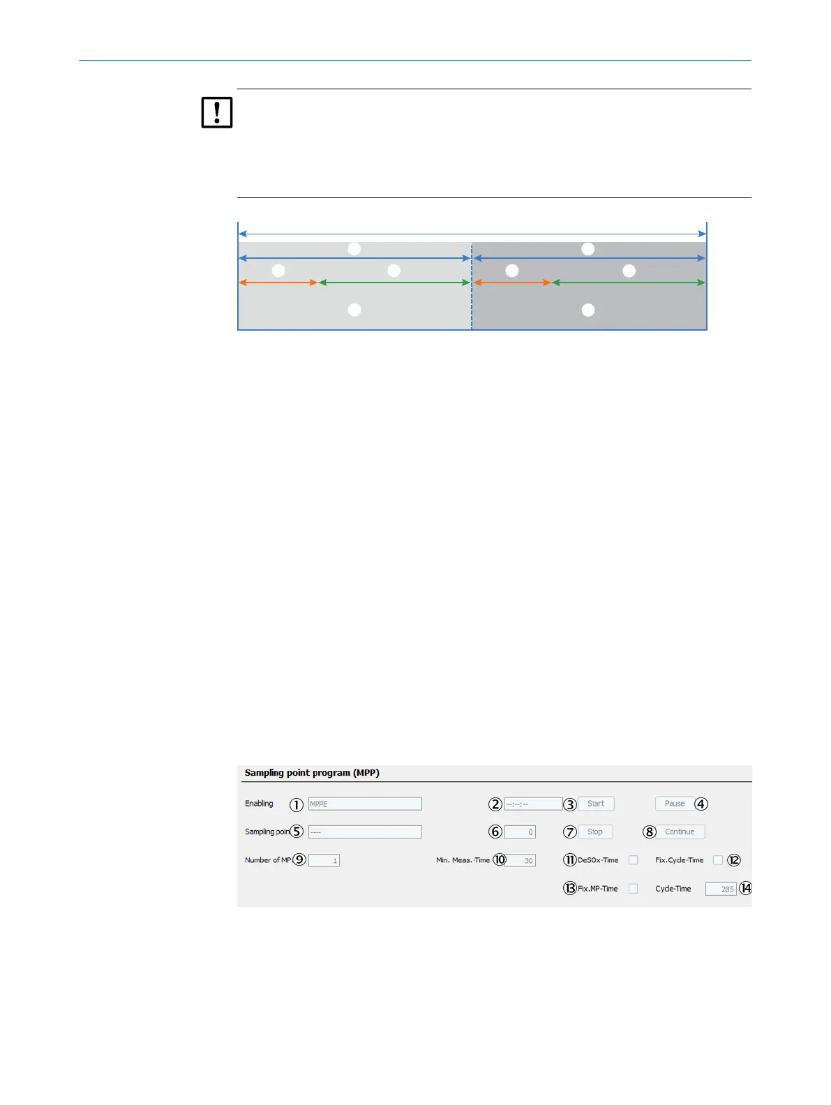
Figure 73: Measuring point switchover - diagram
1
Measuring point 1
2
Measuring point 2
3
Hold time
4
Active
5
Duration
6
Cycle time
Cycle time
The complete defined measuring cycle including measuring point switchover is com‐
pleted within the cycle time.
Duration
The time during which a measuring point is active and measuring (including run-in time
after measuring point switchover).
Hold time
After measuring point switchover: The time in which the last valid measured value of
the measuring point is held until the new measuring point has run-in (purge processes
etc.).
The hold time can be entered individually for each measuring point and serves, for
example, to control the release of the measured value to Modbus or similar.
Active
Valid measured values of the active measuring point are available after the run-in time.
Figure 74: Menu Sampling point program (MPP)
1
Display: Internal tag to enable the sampling point program
2
Display: Run-time for the current sampling point
3
Start the sampling point program
4
Interrupt the sampling point program (pause)
5
Display: Active sampling point
6
Display: Index of active sampling point
PARAMETERIZATION 6
8017585/YXD9/V3-1/2017-05 | SICK T E C H N I C A L I N F O R M A T I O N | MARSIC300
53
Subject to change without notice