Connecting Extensions to the System’s Internal MDF (Main Distribution Frame
A31003-K1250-S100-12-7619
HiPath 1100, Service Manual
4-37
For internal distribution only Installation
Example:
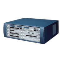
Due to the flexibility of the HiPath 1190 systems, the configuration of expansion and
option modules can vary according to each client’s needs. Here is an example of a
possible configuration:
For a system with a TME1 module in slot 1 and an EB 012 module in slot 3. The Main
Distribution Frame would be configured as follows:
Table 4-6 Example of extension locations on the Main Distribution Frame
Module Slot
External Digital
Line Number
Extension
Slot
Internal
Number
TME1 Slot 1 01 to 30 --- 801 to 830
EB 012 Slot 3 --- 1 to 12 101 to 112
Figure 4-30 Distribution of extensions on the HiPath 1190/1190R Main Distribution Frame
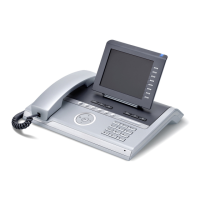
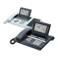
*The installation of a system telephone requires using a CD pair in conjunction with an a/b
extension slot (see “Installing Telephone Terminals” on page 4-46).
 Loading...