Iso-center with ultrasound 6 - 15
Siemens AG SPL1-130.840.02 Page 15 of 16 MODULARIS Uro Plus
Medical Solutions Rev. 03 04.05 CS PS 24
• Set all slide controls all the way to the left.
• The image flip key may not be selected.
• Select the appropriate ultrasound probe:
• Check whether the ultrasound arm is as shown in Fig. 22; if not, position it accordingly.
The long slot must be visible (1/Fig. 22).
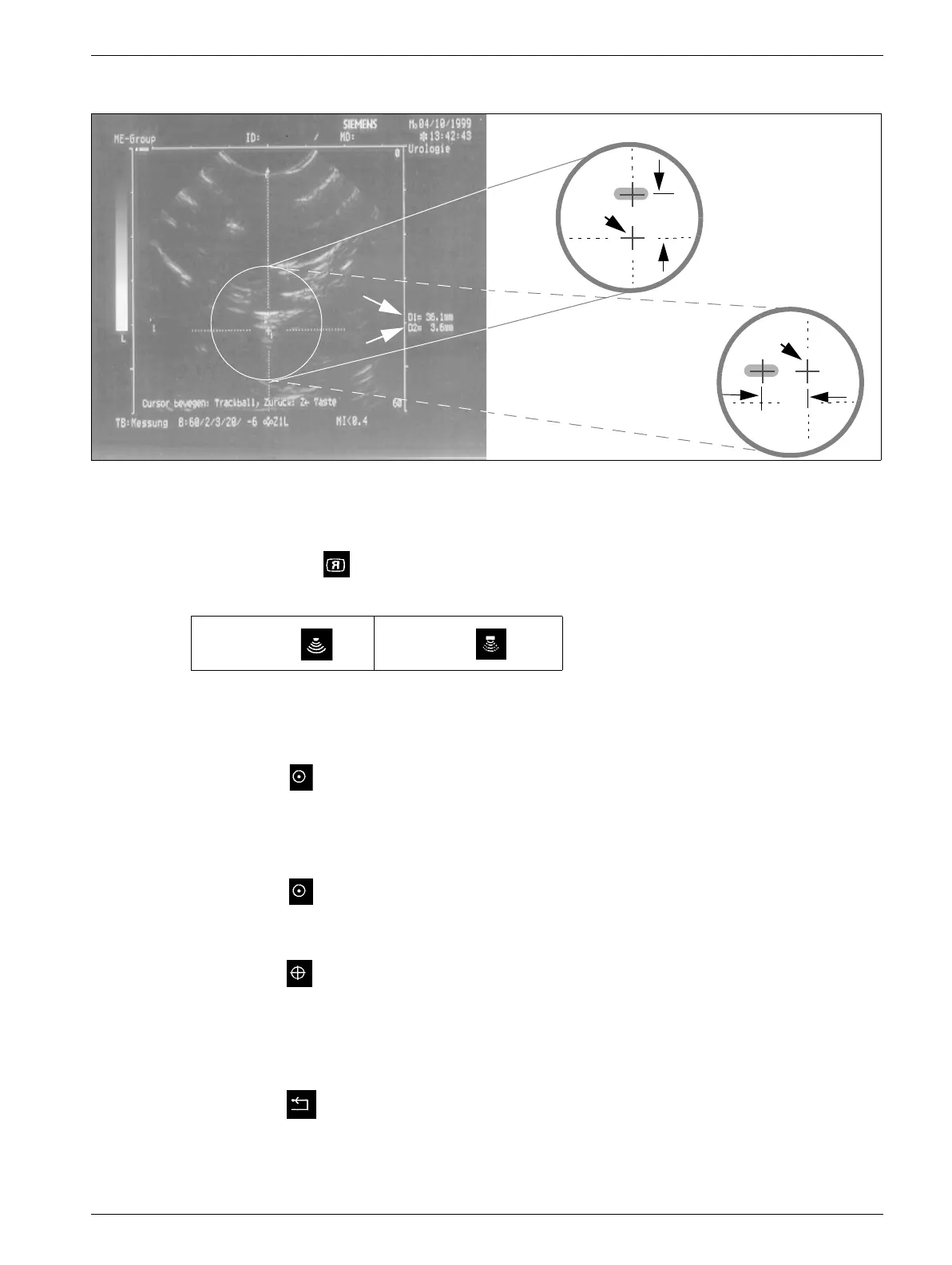
Checking the distance: Height (23a/Fig. 23)
• Press the key.
• Move the track ball until the corss "+1" is in the center of the isocenter crosshair.
• The value displayed for "D1" (G/Fig. 23) must be between 33 and 36 mm; if not, move the
probe appropriately in the longitudinal axis.
• Press the key.
• Move the cross "+2" using the track ball onto the longitudinal axis of the target line in the
isocenter (M/Fig. 23a).
• Press the key.
• Move the cross "+2" using the track ball horizontally into the center of the white area
(23a/Fig. 23) of the isocenter phantom
• The value displayed for "D2" (H/Fig. 23) must be between 1 and 5 mm. This is only valid
for the default values, see instructions, SPL1-130.038.01...
• Press the key.
Fig. 23
Sector probe Array probe
A
B
C
D
2
Image detail sche-
matic
:
2
C
23a
23b
M
C
G
H