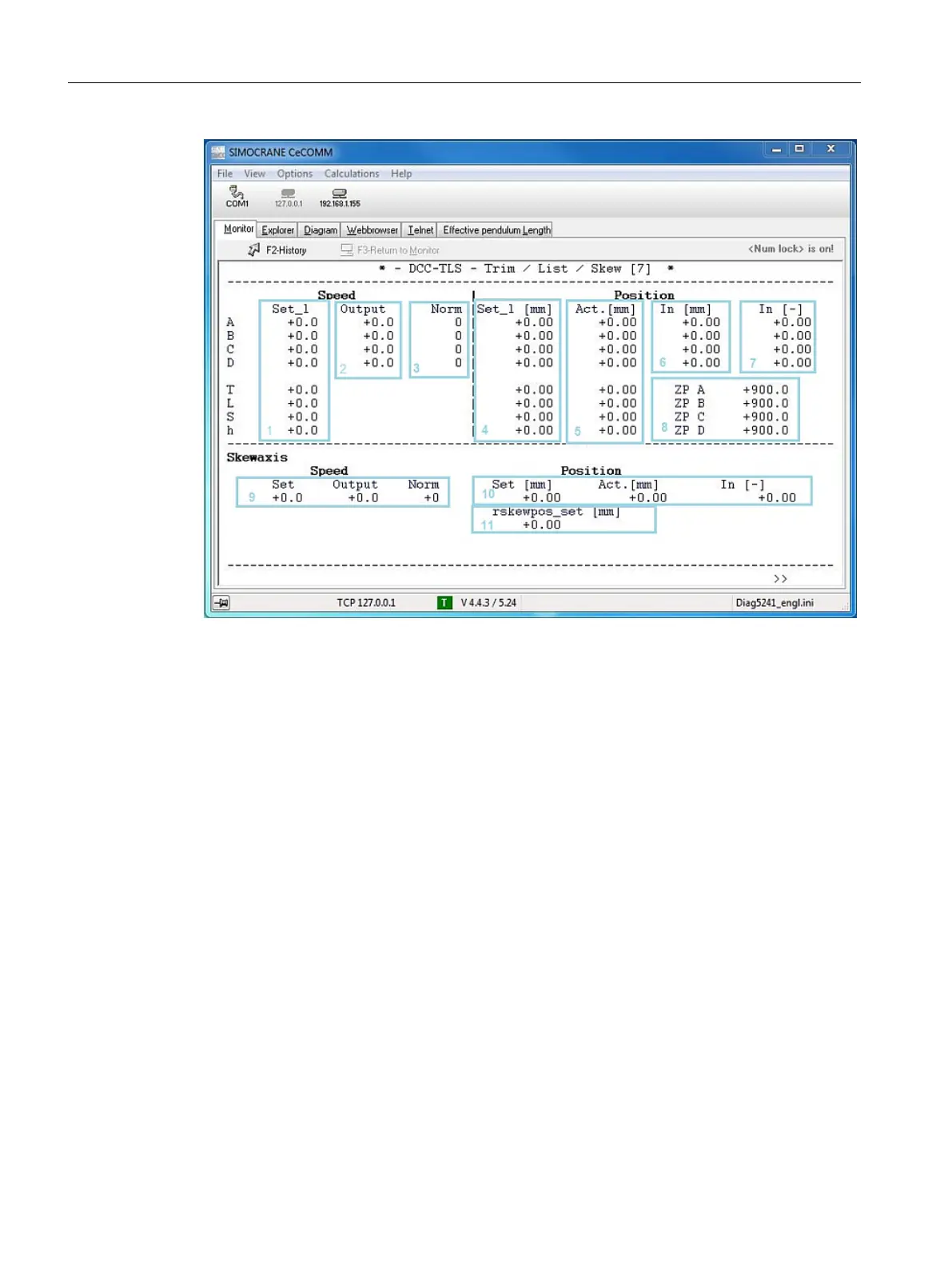
Figure 8-16 Monitor 7
The marked areas have the following signals:
1 v_set_b_ABCD, v_set_b_TLSh (mm/s)
2 v_out_ABCD (mm/s)
3 v_out_norm_ABCD
4 s_set_b_abcd, s_set_b_TLSh
5 s_act_abcd, s_act_TLSh
6 pos_cal_A, pos_cal_B, pos_cal_C, pos_cal_D
7 Input DCC block DCC_SCTLS2: rpos_a, rpos_b, rpos_c, rpos_d
8 Zero positions P250 to P253
Note: The parameters for the skew axis in the lower monitor section are only visible if the
electric drive is activated with P320=1.
9 v_set_SkA (mm/s), v_out_SkA (mm/s), v_out_norm_SkA
10 s_set_SkA, s_act_SkA, rpos_skewaxis
11 Input of the DCC block rskewpos_set
Monitor 8
Monitor 8 shows information about skew oscillation, the selected travel mode, and current
target positions.
SIMOCRANE CeCOMM commissioning and diagnostic program
8.5 Monitor (tab)
SC integrated STS, GSU
280 Operating Instructions, 07/2019, A5E48271265B AA
 Loading...