Number Name Factory setting
p0861 Line contactor monitoring time 100ms
p1226[D] Speed threshold for standstill detection 20rpm
p1227 Standstill detection monitoring time 300 s
p1228 Pulse suppression delay time 0.01 s
8.4 Adapt the default setting of the terminal strip
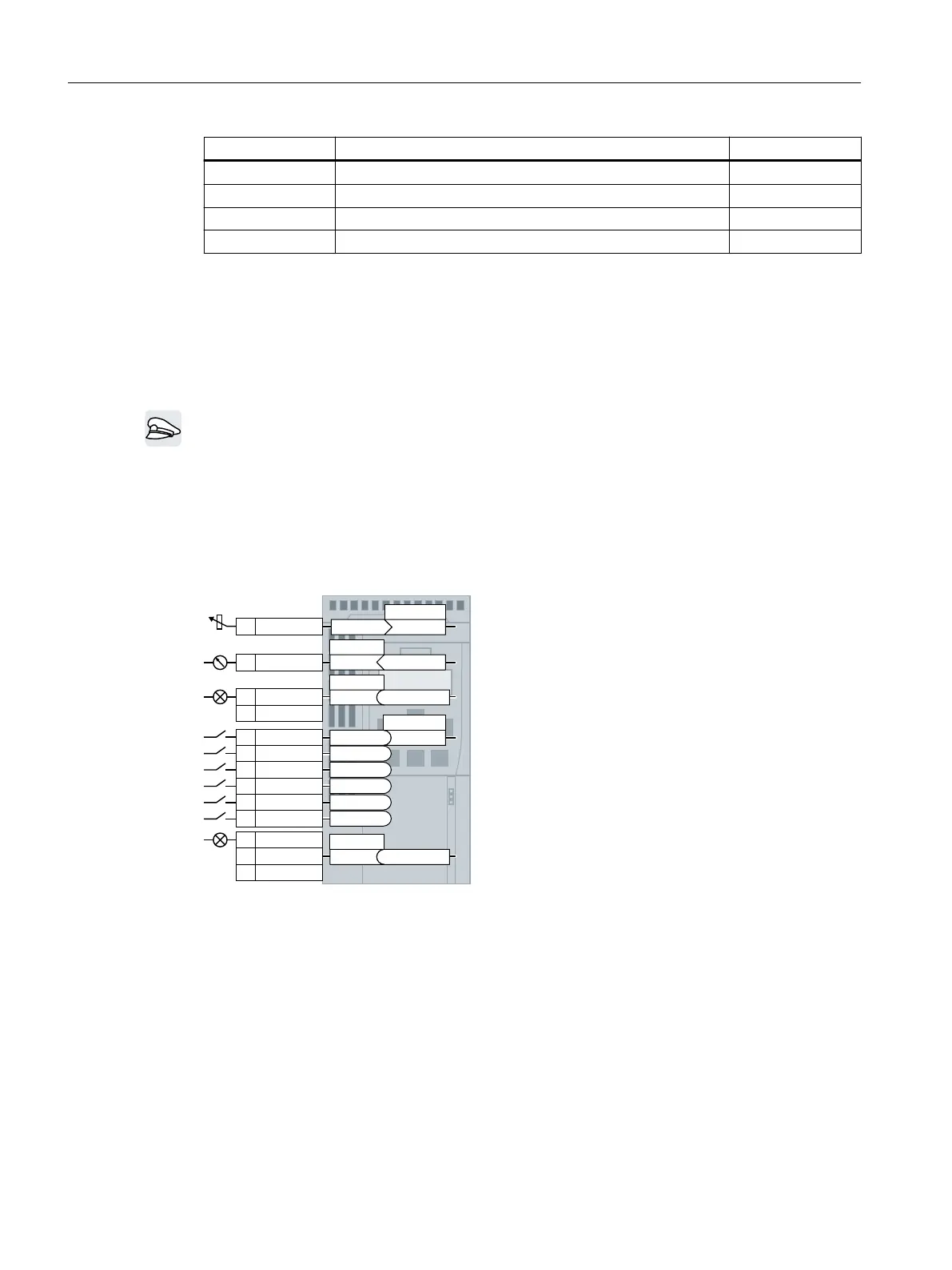
Overview
In the converter, the input and output signals are interconnected with specic converter
functions using special parameters. The following parameters are available to interconnect
signals:
• Binectors BI and BO are parameters to interconnect binary signals.
• Connectors CI and CO are parameters to interconnect analog signals.
The following chapters describe how you adapt the function of individual converter inputs
and outputs using binectors and connectors.
U
&,S\\\\
$,
$2
'2
'2
',
',
',
',
',
',
'212
'2&20
'21&
&2U[[\\
S
U
U
U
U
U
U
%,S[[[[
%2U\\[[Q
%2U\\[[Q
S
S
Figure8-4 Interconnecting the inputs and outputs in the converter
Advanced commissioning
8.4Adapt the default setting of the terminal strip
SINAMICS G120C Converters
188 Operating Instructions, 02/2023, FW V4.7 SP14, A5E34263257B AK
 Loading...


