8.20.3 Sensorless vector control
8.20.3.1 Structure of vector control without encoder (sensorless)
Overview
The vector control comprises closed-loop current control and a higher-level closed-loop speed
control.
,GFRQWUROOHU
,TFRQWUROOHU
6SHHGVHWSRLQW
&DOFXODWHGVSHHG
DFWXDOYDOXH
0RWRUDQGFXUUHQWPRGHO
&DOFXODWH
VSHHGOLPLWV
7RUTXH
VHWSRLQW
0HDVXUHG
YROWDJH
0HDVXUHG
FXUUHQW
2XWSXWIUHTXHQF\
2XWSXWYROWDJH
9ROWDJHDQJOH
6OLS
6SHHGFRQWUROOHU
7RUTXH
SUHFRQWURO
0D[LPXPVSHHG
&DOFXODWHDFFHOHUD
WLRQWRUTXH
7UDQVIRU
PDWLRQ
7UDQVIRU
PDWLRQ
)OX[VHWSRLQW
8SSHUWRUTXHOLPLW
/RZHUWRUTXHOLPLW
&XUUHQWOLPLW
3RZHUOLPLWZKHQJHQHUDWLQJ
6WDWLFWRUTXHVHWSRLQW
6XSSOHPHQWDU\DFFHOHUDWLRQWRUTXH
3RZHUOLPLWZKHQPRWRULQJ
&DOFXODWH
WRUTXHOLPLWV
S
.
3
7
,
S
S
S
S
S
S
S
1)
for induction motors
2)
Settings that are required
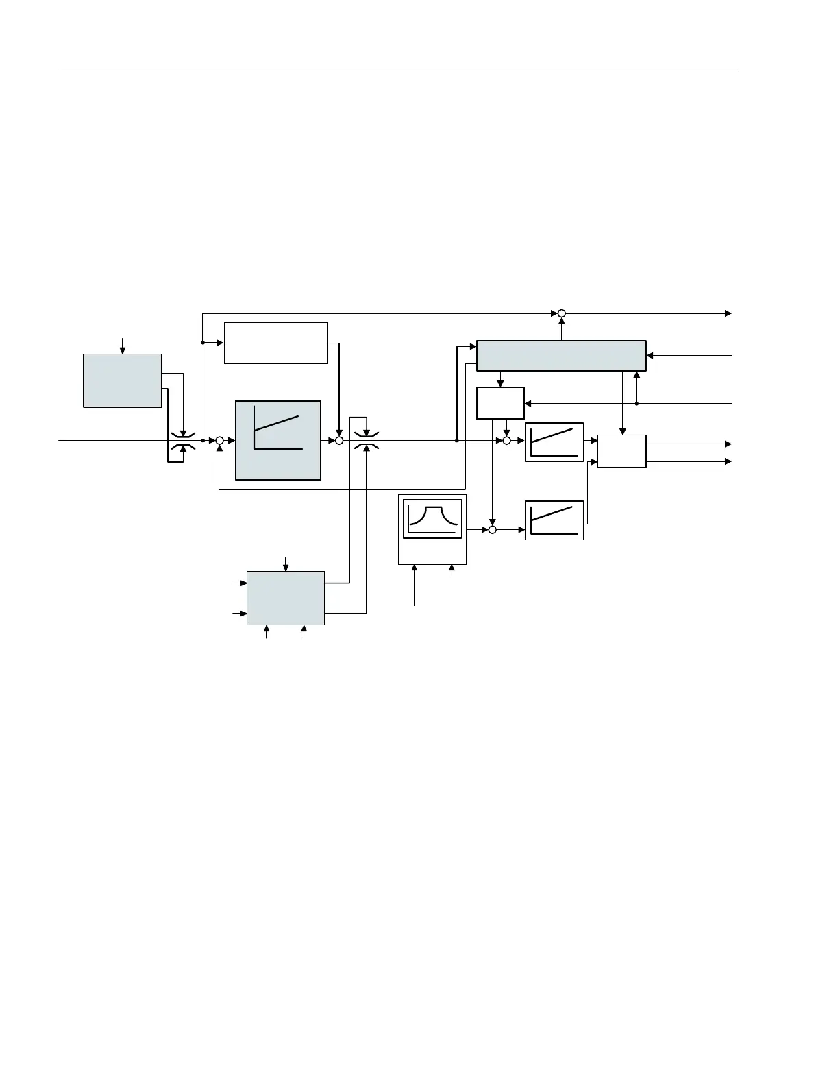
Figure8-52 Simplied function diagram for sensorless vector control with speed controller
Using the motor model, the converter calculates the following closed-loop control signals
from the measured phase currents and the output voltage:
• Current component I
q
• Current component I
q
• Speed actual value
The setpoint of the current component I
d
(ux setpoint) is obtained from the motor data.
For speeds above the rated speed, the converter reduces the ux setpoint along the eld
weakening characteristic.
When the speed setpoint is increased, the speed controller responds with a higher setpoint
for current component I
q
(torque setpoint). The closed-loop control responds to a higher
torque setpoint by adding a higher slip frequency to the output frequency. The higher output
frequency also results in a higher motor slip, which is proportional to the accelerating torque.
Advanced commissioning
8.20Motor control
SINAMICS G120C Converters
310 Operating Instructions, 02/2023, FW V4.7 SP14, A5E34263257B AK
 Loading...


