Alarms, faults and system messages
9
The converter has the following diagnostic types:
• LED
The LEDs at the front of the converter immediately inform you about the most important
converter states.
• Alarms and faults
Every alarm and every fault has a unique number.
The converter signals alarms and faults via the following interfaces:
– Fieldbus
– Terminal strip with the appropriate setting
– Interface to the BOP-2 or IOP‑2 operator panel
– Interface to STARTER or Startdrive
• Identication & maintenance data (I&M)
If requested, the converter sends data to the higher-level control via PROFIBUS or PROFINET:
– Converter-specic data
– Plant-specic data
9.1 Operating states indicated via LEDs
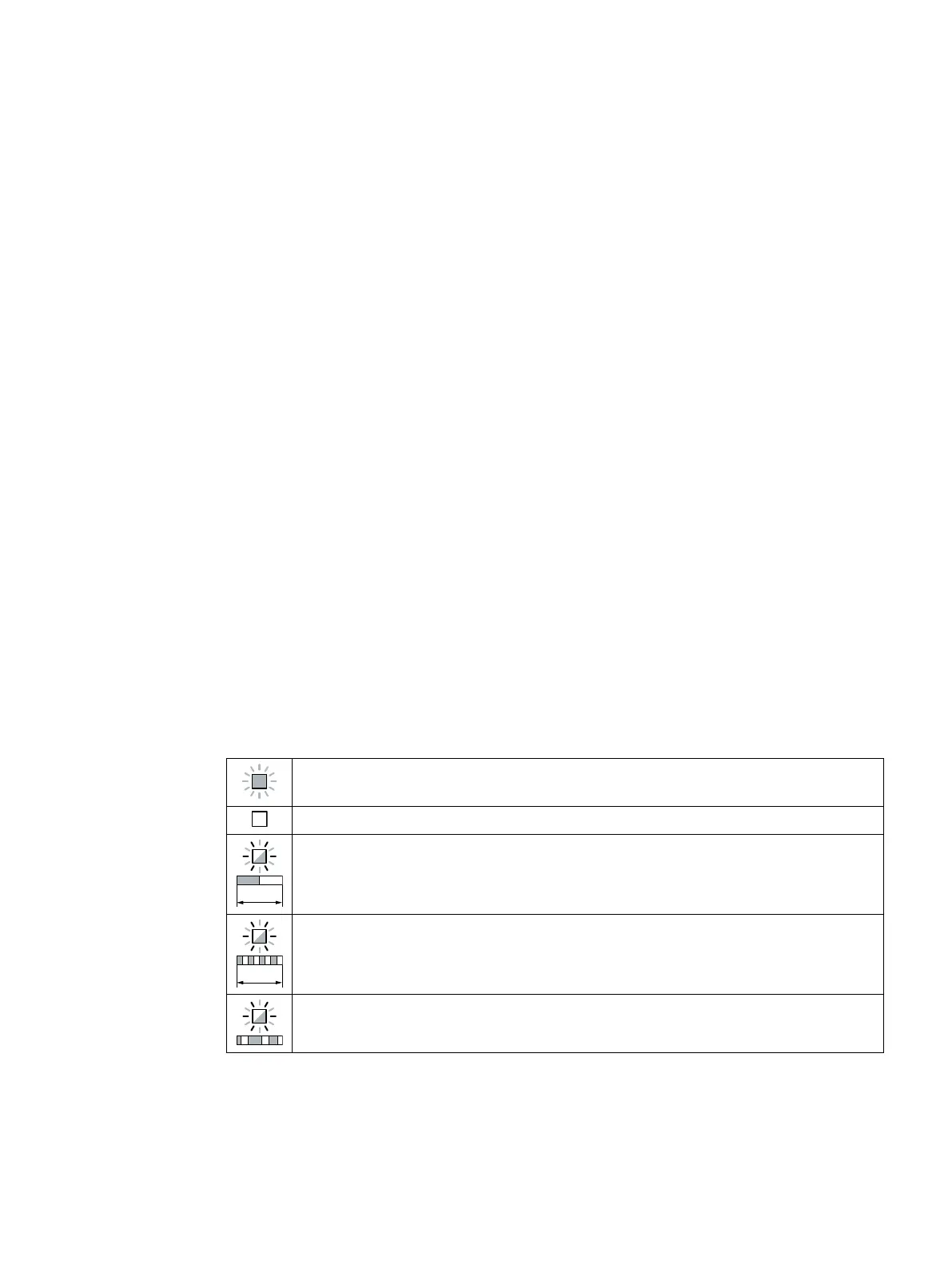
Table 9-1 Explanation of symbols for the following tables
LED is ON
LED is OFF
LED ashes slowly
LED ashes quickly
LED ashes with variable frequency
Please contact Technical Support for LED states that are not described in the following.
SINAMICS G120C Converters
Operating Instructions, 02/2023, FW V4.7 SP14, A5E34263257B AK 361
 Loading...


