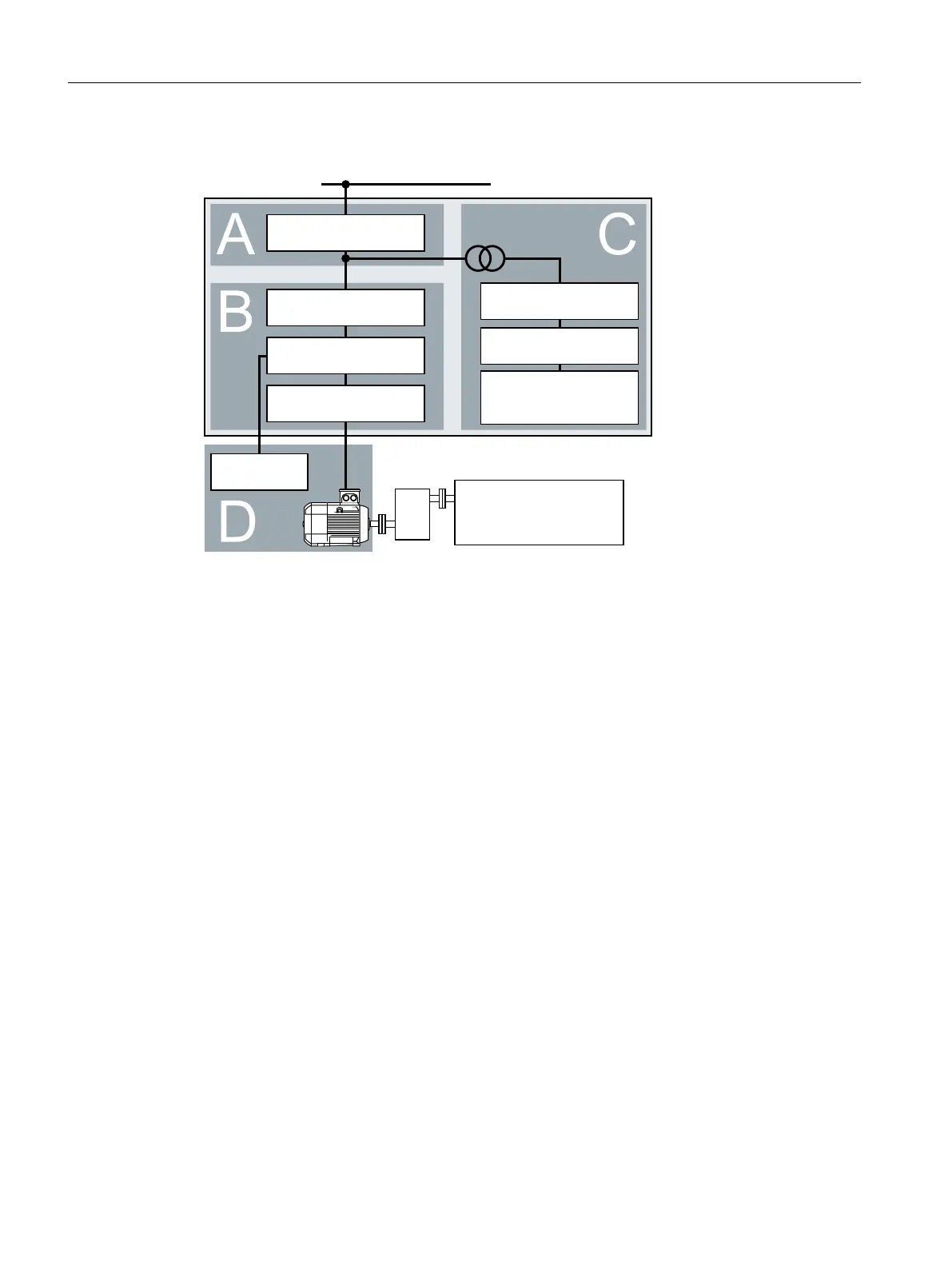
EMC zones
)XVHVVZLWFKHVDQG
FRQWDFWRUV
9SRZHUVXSSO\
+LJKHUOHYHOFRQWURO
V\VWHP
&RQQHFWLRQRIVHQVRUV
HJSRVLWLRQSUHVVXUHRU
WHPSHUDWXUH
/LQHUHDFWRURUOLQHILOWHU
&RQYHUWHU
%UDNLQJUHVLVWRU
2XWSXWUHDFWRURU
VLQHZDYHILOWHU
&RQWUROFDELQHW
/LQHVXSSO\
'ULYHQPDFKLQH
Figure4-2 Example of the EMC zones of a plant or machine
Inside the control cabinet
• Zone A: Line supply connection
• Zone B: Power electronics
Devices in ZoneB generate energy-rich electromagnetic elds.
• Zone C: Control and sensors
Devices in Zone C do not generate any energy-rich electromagnetic elds themselves, but
their functions can be impaired by electromagnetic elds.
Outside the control cabinet
• Zone D: Motors, braking resistors
Devices in ZoneD generate electromagnetic elds with a signicant amount of energy
4.2.1 Control cabinet
• Assign the various devices to zones in the control cabinet.
• Electromagnetically uncouple the zones from each other by means of one of the following
actions:
– Side clearance ≥ 25cm
– Separate metal enclosure
– Large-area partition plates
• Route cables of various zones in separate cable harnesses or cable ducts.
• Install lters or isolation ampliers at the interfaces of the zones.
Installing
4.2EMC-compliant setup of the machine or plant
SINAMICS G120C Converters
40 Operating Instructions, 02/2023, FW V4.7 SP14, A5E34263257B AK
 Loading...


