Additional requirements placed on the protective conductor ① according to IEC60204-1:
• For permanent connection, the protective conductor must fulll at least one of the following
conditions:
– The protective conductor is routed so that it is protected against damage along its
complete length.
Cables routed inside switch cabinets or enclosed machine housings are considered to be
adequately protected against mechanical damage.
– As a conductor of a multi-conductor cable, the protective conductor has a cross-section ≥
2.5mm² Cu.
– For an individual conductor, the protective conductor has a cross-section ≥ 10mm² Cu.
– The protective conductor consists of 2 individual conductors with the same cross-section.
• When connecting a multi-core cable using an industrial plug connector according to
EN60309, the protective conductor must have a cross-section of ≥2.5mm²Cu.
• Observe the local regulations for protective conductors subject to a high leakage current at
the installation site.
4.9.3 Installation after a long storage time
Overview
To avoid extra duties, Siemens recommends to run the converter for an hour with 100% main
supply voltage once a year. If the converter has not been in operation for too long, you must form
the DC link capacitors before switching the full mains voltage to the converter.
Precondition
Form the DC-link capacitors in the following cases:
• The converter was not operational for longer than one year.
• The date of manufacture of the converter was more than one year ago when installing the
converter for the rst time.
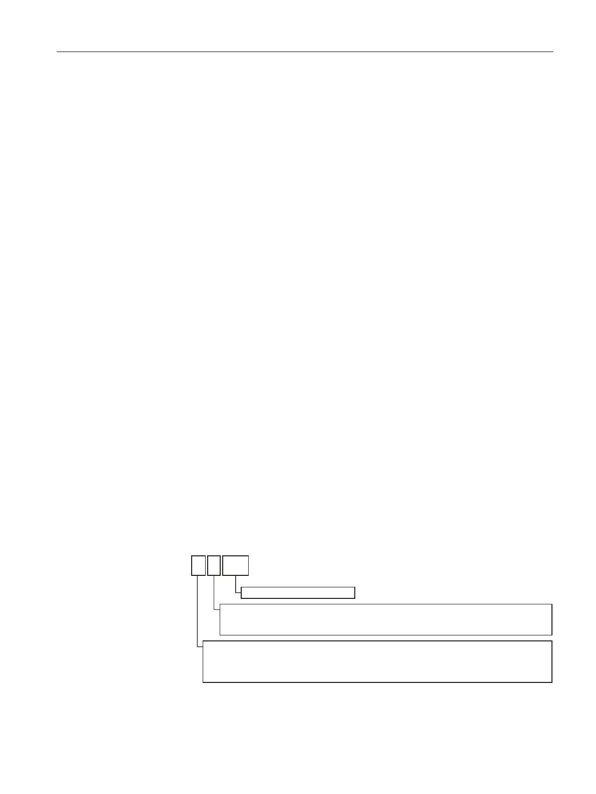
The date of manufacture of the converter is coded in positions 3 - 6 of the serial number.
'D\RIPDQXIDFWXUH
0RQWKRIPDQXIDFWXUH
-DQXDU\ 0DUFK 0D\ -XO\ 6HSWHPEHU11RYHPEHU
)HEUXDU\ $SULO -XQH $XJXVW22FWREHU''HFHPEHU
Year of manufacture
A 2010 D 2013 H 2016 L 2019 P 2022 T 2025 W 2028
B 2011 E 2014 J 2017 M 2020 R 2023 U 2026 X 2029
C 2012 F 2015 K 2018 N 2021 S 2024 V 2027
S N- D 4 2 1 1 2 3 4 5 6
Figure4-25 Data of manufacture in the serial number (example, April 21, 2013)
Installing
4.9Connect the line supply, motor and braking resistor
SINAMICS G120C Converters
Operating Instructions, 02/2023, FW V4.7 SP14, A5E34263257B AK 69
 Loading...


