10.6 Reduced acceptance after component replacement and
rmware change
After a component has been replaced or the rmware updated, a reduced acceptance test of the
safety functions must be performed.
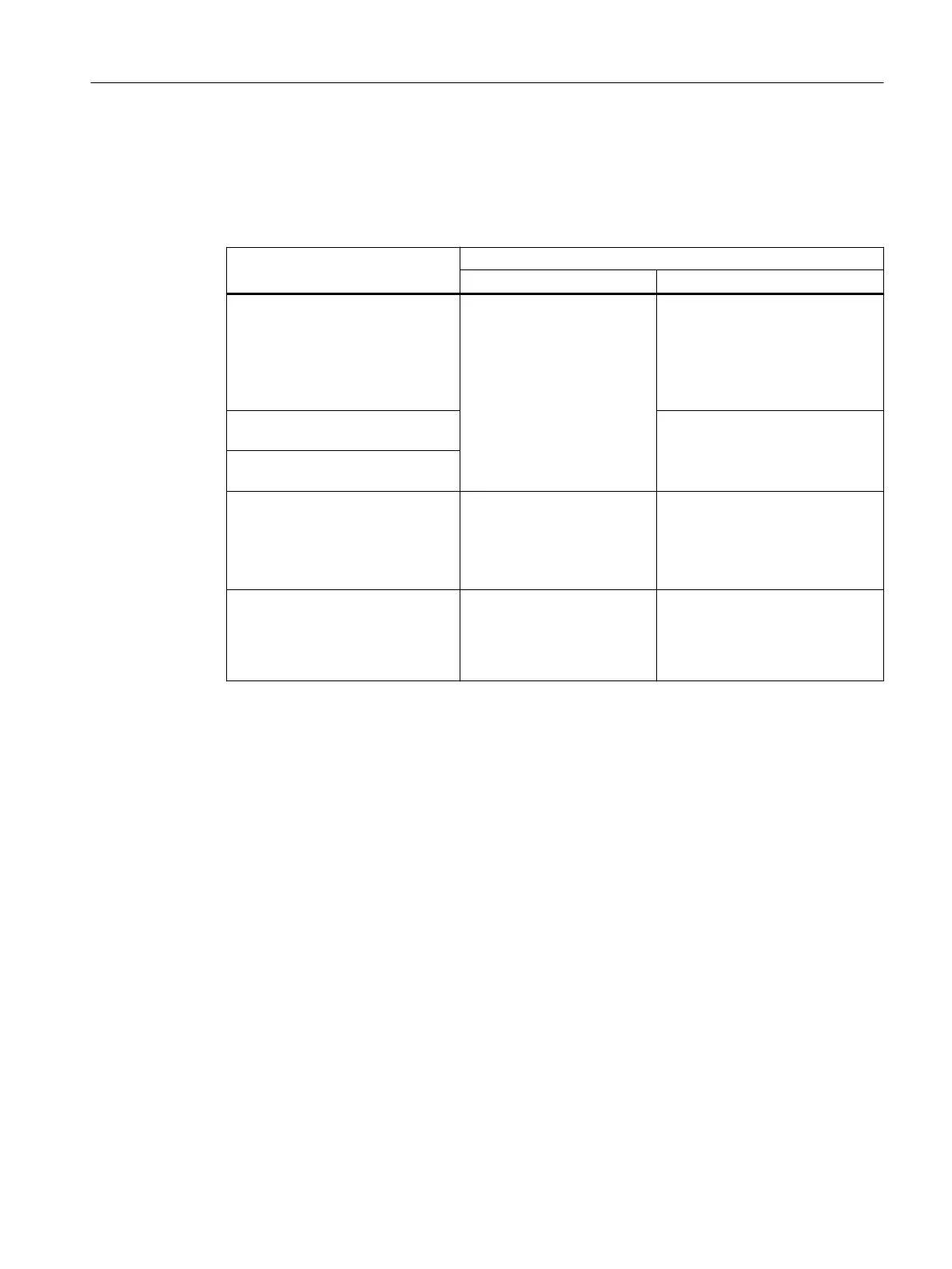
Measure Reduced acceptance test
Acceptance test Documentation
Replacing the converter with an
identical type
No.
Only check the direction of ro‐
tation of the motor.
• Supplement the converter data
• Log the new checksums
• Countersignature
• Supplement the hardware ver‐
sion in the converter data.
Replacing the motor with an identi‐
cal pole pair number
No change.
Replace the gearbox with an identi‐
cal ratio
Replacing safety-related I/O devices
(e.g. Emergency Stop switch).
No.
Only check the control of the
safety functions aected by
the components that have
been replaced.
No change.
Converter rmware update. No.
• Supplement rmware version
in the converter data
• Log the new checksums
• Countersignature.
Corrective maintenance
10.6Reduced acceptance after component replacement and rmware change
SINAMICS G120C Converters
Operating Instructions, 02/2023, FW V4.7 SP14, A5E34263257B AK 417
 Loading...


