8.4.5 Analog input
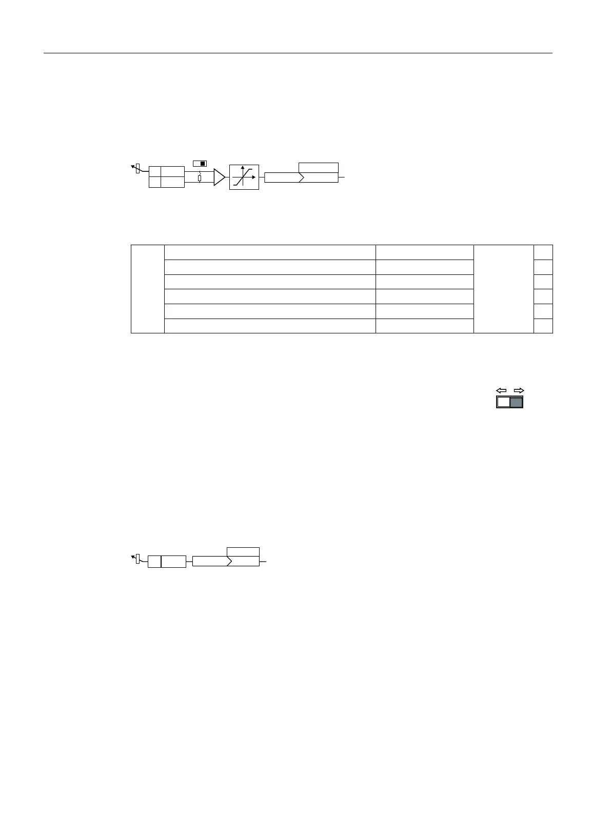
Function description
S>@
U
&,S\\\\
$,
$,
,8
Dening the analog input type
The parameter p0756[x] and the switch on the converter specify the analog input type.
AI 0 Unipolar voltage input 0V…+10V p0756[0]= 0
Unipolar voltage input monitored +2V…+10V 1
Unipolar current input 0mA…+20mA 2
Unipolar current input monitored +4mA…+20mA 3
Bipolar voltage input ‑10V…+10V 4
No sensor connected --- 8
In addition, you must also set the switch associated with the analog input. You can nd the
switch on the Control Unit behind the front doors.
• Voltage input: Switch position U (factory setting)
• Current input: Switch position I
Dening the function of an analog input
You dene the analog input function by interconnecting a connector input of your choice
with parameter p0755. Parameter p0755 is assigned to the particular analog input via its
index, e.g. parameter p0755[0] is assigned to analog input0.
Connector inputs are designated in the parameter list with "CI".
Example
$,
U>@>@
S
In order to enter the supplementary setpoint via analog input AI0, you must interconnect
AI0 with the signal source for the supplementary setpoint.
Set p1075=755[0].
Advanced commissioning
8.4Adapt the default setting of the terminal strip
SINAMICS G120C Converters
194 Operating Instructions, 02/2023, FW V4.7 SP14, A5E34263257B AK
 Loading...


