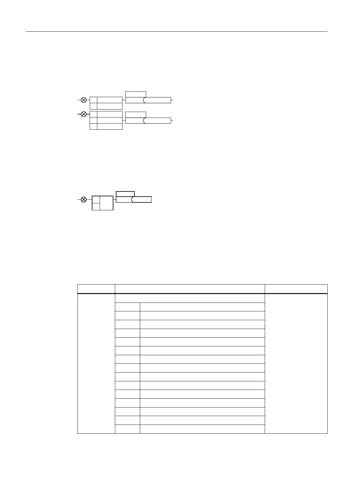
8.4.4 Digital outputs
Function description
'2
'2
'212
'2&20
'21&
%2U\\[[Q
%2U\\[[Q
S
S
To change the function of a digital output, you must interconnect the digital output with a
binector output of your choice.
Binector outputs are designated in the parameter list with "BO".
Example
To output converter fault messages via digital output DO1, you must interconnect DO1 with
these fault messages.
Set p0731=52.3
Parameter
Table 8-3 Frequently used binector outputs (BO) of the converter
Parameter Description Factory setting
r0052[0...15] CO/BO: Status word 1 -
.00 1 signal: Ready for switching on
.01 1 signal: Ready for operation
.02 1 signal: Operation enabled
.03 1 signal: Fault active
.04 0 signal: OFF2 active
.05 0 signal: OFF3 active
.06 1 signal: Switching on inhibited active
.07 1 signal: Alarm active
.08 0 signal: Deviation, setpoint/actual speed
.09 1 signal: Control request
.10 1 signal: Maximum speed (p1082) reached
.11 0 signal: I, M, P limit reached
.13 0 signal: Alarm, motor overtemperature
.14 1 signal: Motor clockwise rotation
.15 0 signal: Alarm, converter overload
Advanced commissioning
8.4Adapt the default setting of the terminal strip
SINAMICS G120C Converters
192 Operating Instructions, 02/2023, FW V4.7 SP14, A5E34263257B AK
 Loading...


