Example
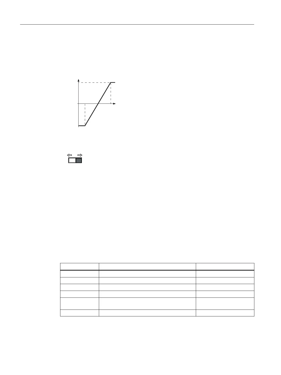
The converter should convert a 6mA…12mA signal into the value range ‑100%…100% via
analog input 0. The wire-break monitoring of the converter should respond when 6 mA is fallen
below.
&XUUHQWLQSXWP$P$
[
S
\
S
[
S
\
S
P$
Procedure
1. Set the DIP switch for analog input 0 on the Control Unit to current input ("I").
2. set p0756[0]=3
You have dened analog input0 as a current input with wire-break monitoring.
3. Set p0757[0] = 6.0 (x1)
4. Set p0758[0] = -100.0 (y1)
5. Set p0759[0] = 12.0 (x2)
6. Set p0760[0] = 100.0 (y2)
7. Set p0761[0]=6
An input current<6mA results in fault F03505.
The characteristic for the application example is set.
❒
Parameters
Parameter Description Factory setting
p0757[0…n] CU analog inputs characteristic value x1 0
p0758[0…n] CU analog inputs characteristic value y1 0%
p0759[0…n] CU analog inputs characteristic value x2 10
p0760[0…n] CU analog inputs characteristic value y2 100%
p0761[0…n] CU analog inputs wire-break monitoring, response
threshold
2
p0762[0…n] CU analog inputs wire breakage monitoring time 100ms
Advanced commissioning
8.4Adapt the default setting of the terminal strip
SINAMICS G120C Converters
196 Operating Instructions, 02/2023, FW V4.7 SP14, A5E34263257B AK
 Loading...


