Debounce time
In the following cases, an immediate converter response to signal changes of the failsafe
digital inputs is not desirable:
• If a failsafe digital input of the converter is interconnected with an electromechanical sensor,
brief signal changes can occur due to contact bounce.
• In order to identify faults due to short-circuit or cross faults, several control modules test their
failsafe digital outputs with "bit pattern tests" (on/o test). If a failsafe digital input of the
converter is interconnected with a failsafe digital output of an open-loop control module,
then the converter responds with a bit pattern test.
The typical duration of the signal change within a bit pattern test:
– On test: 1ms
– O test: 4ms
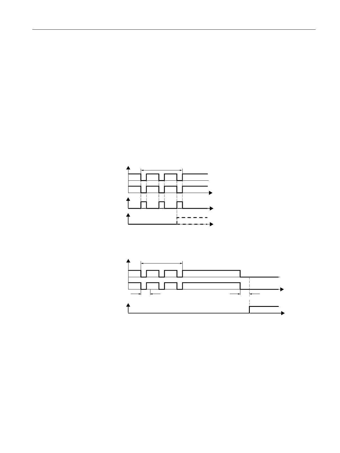
Too many signal changes within a specic time result in a converter fault.
)',LQSXWVLJQDOV
6DIHW\IXQFWLRQDFWLYH
)DXOW)
%LWSDWWHUQWHVW
W
W
W
Figure8-29 Converter response to a bit pattern test
You must set the debounce time to ignore temporary signal changes.
)',LQSXWVLJQDOV
6DIHW\IXQFWLRQDFWLYH
'HERXQFHWLPH
%LWSDWWHUQWHVW
'HERXQFHWLPH
W
W
Figure8-30 Filter to suppress brief signals
The debounce time extends the response time of the safety function.
Further information
Debounce times for standard and safety functions
The debounce time p0724 for "standard" digital inputs has no inuence over the failsafe
input signals. Conversely, the same applies: The F-DI debounce time does not aect the
signals of the "standard" inputs.
If you use an input as a standard input, set the debounce time using parameter p0724 .
Advanced commissioning
8.16Safe Torque O (STO) safety function
SINAMICS G120C Converters
Operating Instructions, 02/2023, FW V4.7 SP14, A5E34263257B AK 263
 Loading...


