Function description
%UDNLQJUHVLVWRUEUDNLQJSRZHU
%UDNLQJUHVLVWRU
/RDGDFFHOHUDWLQJ0RWRUL]HGRSHUDWLRQ
/RDGEUDNLQJ*HQHUDWLQJRSHUDWLRQ
6SHHG
'&OLQNYROWDJHU
0D[LPXP'&OLQNYROWDJHU
$FWLYDWLRQWKUHVKROGIRUWKHEUDNLQJ
PRGXOH
U
W
W
W
Q
Q
QQ
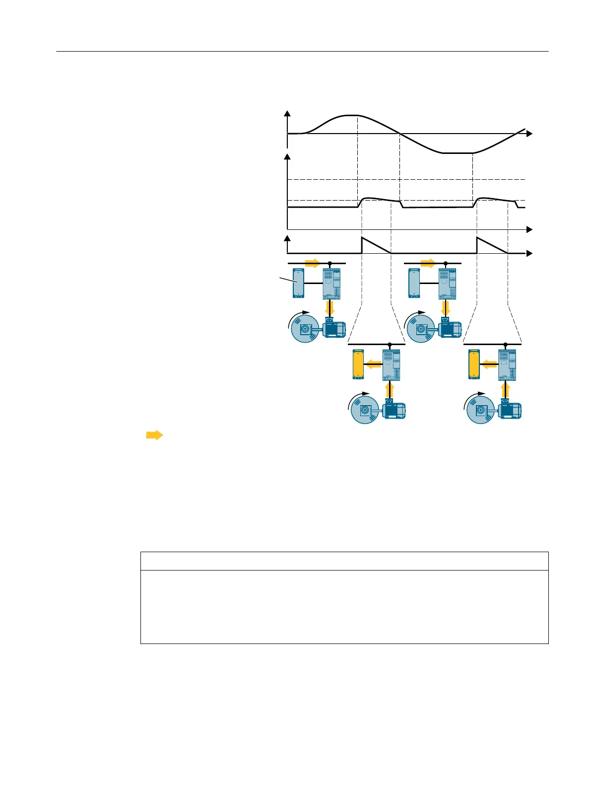
Flow direction of power
Figure8-66 Simplied representation of dynamic braking with respect to time
The motor supplies regenerative power to the converter when braking. The regenerative
power means that the DC-link voltage in the converter increases. Above the activation
threshold for the braking module, the converter forwards the regenerative power to the
braking resistor. The braking resistor converts the regenerative power into heat, thereby
preventing converter faults due to excessive DC-link voltage.
Factory setting for the activation threshold for the braking module: 760V
NOTICE
Overload of motor insulation during braking
When the motor brakes, the DC-link voltage, and thus also the voltage load of the motor,
increases. Under unfavorable circumstances, the converter can overload the motor insulation
and damage the motor.
• Reduce the activation threshold for the braking module
Advanced commissioning
8.21Electrically braking the motor
SINAMICS G120C Converters
Operating Instructions, 02/2023, FW V4.7 SP14, A5E34263257B AK 333
 Loading...


