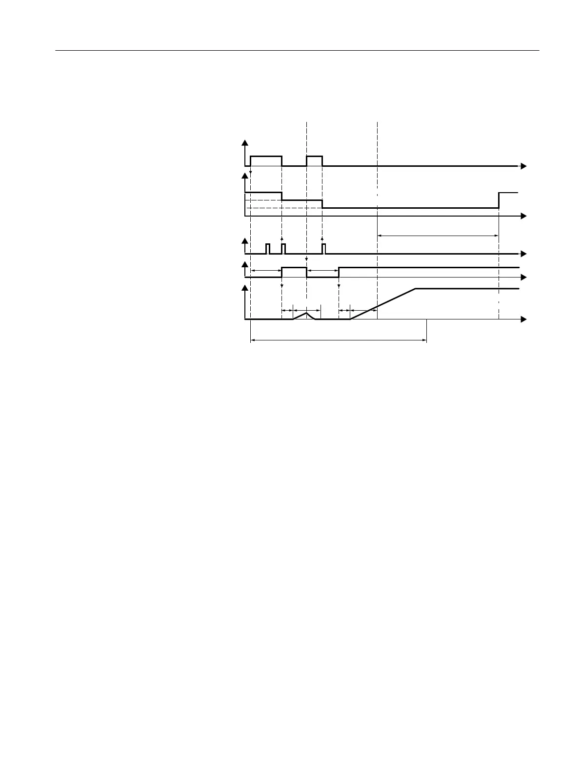
The principle of operation of the other parameters is explained in the following diagram and
in the table below.
,IVWDUWDWWHPSWFRXQWHUWKHQIDXOW
)LVRXWSXW
)DXOWDIWHUSRZHUIDLOXUHRU
LQRSHUDWLRQ
VWVWDUWDWWHPSW
XQVXFFHVVIXOGXH
WRDQHZIDXOW
$VWDUWDWWHPSWPXVWKDYHEHHQVXFFHVVIXOZLWKLQ
S>@,IQRWWKHQIDXOW)LVRXWSXW
$IWHUS>@WKHLQYHUWHUUHVHWV
WKHVWDUWDWWHPSWFRXQWHU
QGVWDUWDWWHPSWLV
VXFFHVVIXO
&RXQWHUVWDUWDWWHPSWV
$XWRPDWLFDFNQRZOHGJPHQW
$XWRPDWLF21FRPPDQG
6SHHG
W
:
VXPRIWKHWLPHVIRUDIO\LQJ
UHVWDUWDQGPDJQHWL]LQJWKH
PRWRU
W
W
W
W
W
S
S
S
V
V
SS
W
:
W
:
1)
The converter automatically acknowledges faults under the following conditions:
• p1210 = 1 or 26: Always.
• p1210 = 4 or 6: If the command to switch-on the motor is available at a digital input or via the
eldbus (ON/OFF1=1).
• p1210 = 14 or 16: Never.
2)
The converter attempts to automatically switch the motor on under the following conditions:
• p1210 = 1: Never.
• p1210 = 4, 6, 14, 16, or 26: If the command to switch-on the motor is available at a digital input or
via the eldbus (ON/OFF1=1).
3)
If, after a ying restart and magnetization (r0056.4 = 1) no fault occurs within one second, then the
start attempt was successful.
Figure8-73 Time response of the automatic restart
Further information is provided in the parameter list.
Advanced settings
If you with to suppress the automatic restart function for certain faults, then you must enter
the appropriate fault numbers in p1206[0 … 9].
Example: p1206[0] = 07331 ⇒ No restart for fault F07331.
Advanced commissioning
8.29Automatic restart
SINAMICS G120C Converters
Operating Instructions, 02/2023, FW V4.7 SP14, A5E34263257B AK 349
 Loading...


