Motor Modules Booksize Compact as expansion axes
6.3 Interface description
146
SINAMICS S120 Combi
Manual, (GH9), 07/2016, 6SL3097-4AV00-0BP5
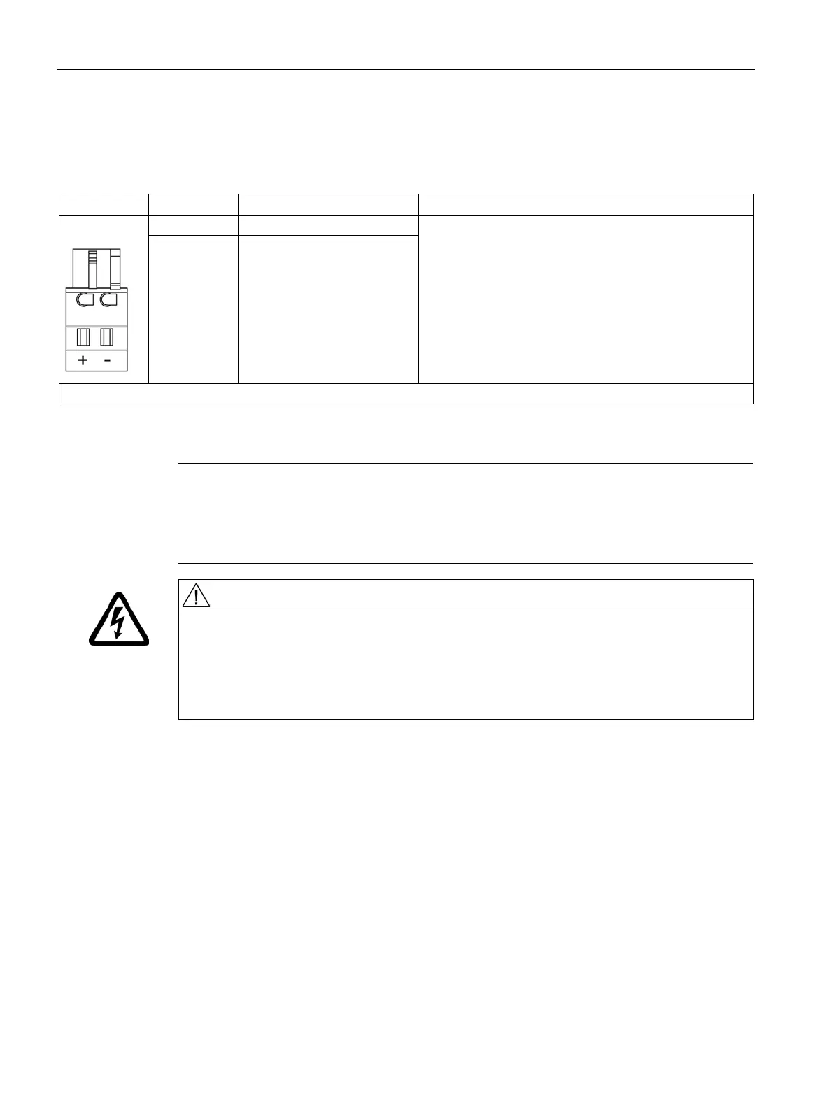
X11/X12 motor brake connection
Table 6- 2 X11/X12 brake connection
Voltage: 24 V DC
Max. load current: 2 A
Minimum load current: 0.1 A
Type: Spring-loaded terminal 1 (Page 306)
Max. cross-section that can be connected: 2.5 mm
2
Manufacturer: Wago
Article number: 721-102/026-000/56-000
BR- Brake connection -
The brake connector is included in the scope of delivery.
The circuit for protecting the brake against overvoltage is integrated in the Motor Module and
does not need to be installed externally.
Note
The motor brake must be connected via connector X11 on Single Motor Modules, and X11
and X12 on Double Motor Modules. The BR
- cable must not be connected directly to
electronics ground (M). The shield of the brake cable
is only to be connected to the shield
Danger to life through electric shock due to a terminal voltage that has not been adjusted
Contact with live parts can result in death or serious injury.
• Connect protective extra-low voltages (PELV) to all connections and terminals betw
een
0 an
d 48 V DC.
• Observe the voltage tolerances of the motor holding brakes (24 V ± 10%).

 Loading...


