S120 Combi Power Modules
4.3 Interface description
88
SINAMICS S120 Combi
Manual, (GH9), 07/2016, 6SL3097-4AV00-0BP5
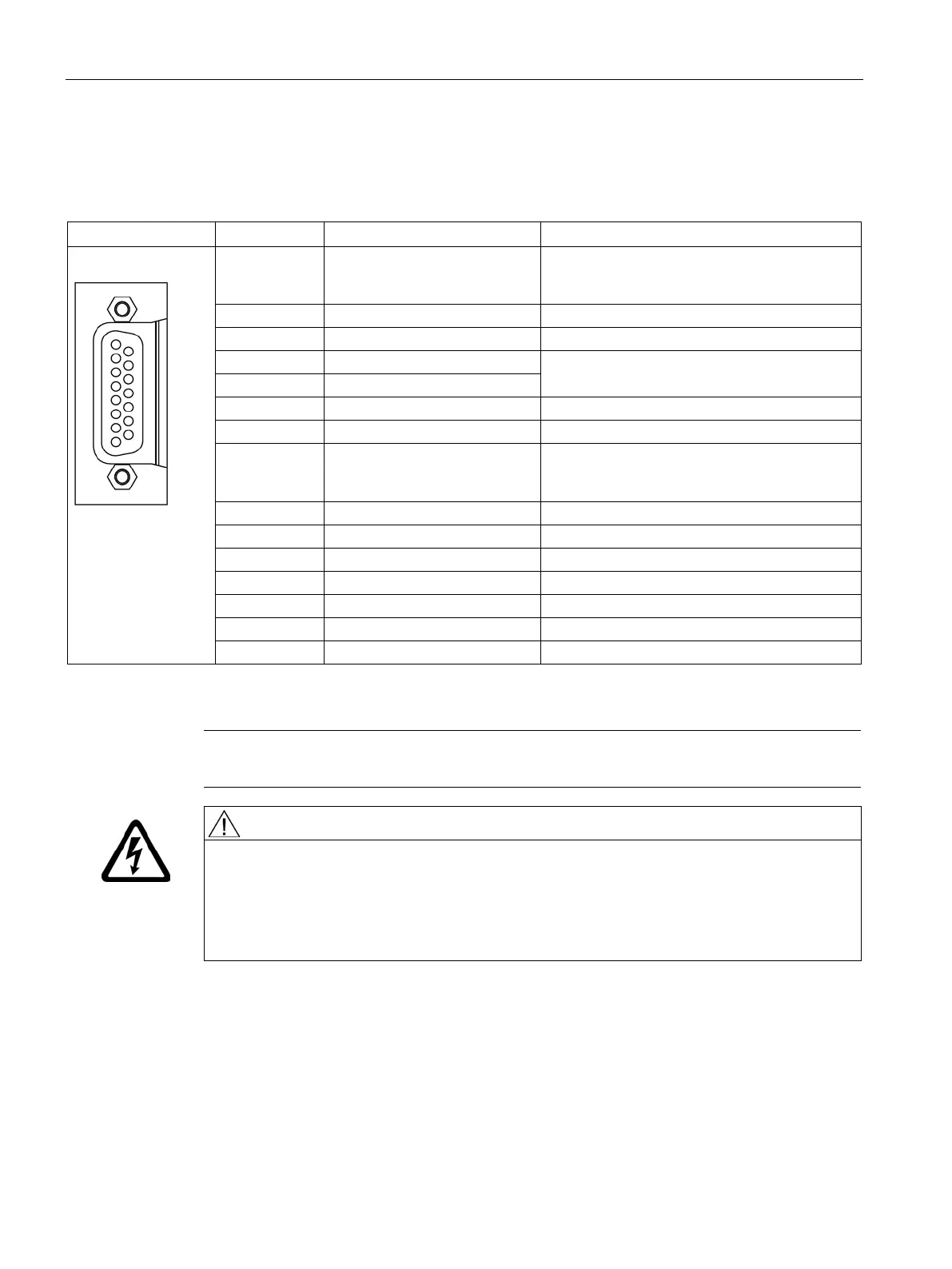
Table 4- 13 Encoder interface X220
1 + Temp Motor temperature sensing
KTY84-1C130 (KTY+)
Temperature sensor KTY84-1C130 / PTC
2 Clock Clock
Encoder power supply
Sense input of encoder power supply
Ground for encoder power supply
8 - Temp Motor temperature sensing
KTY84-1C130 (KTY+)
Temperature sensor KTY84-1C130 / PTC
Inverse reference signal R
Inverse incremental signal B
Inverse incremental signal A
Type: Sub-D socket, 15-pin; TTL encoder; max. cable length 100 m
V TTL encoders are supported.
Danger to life through electric shock due to temperature sensors that are not permitted
If temperature sensors that do not comply with the safety isolation specifications are
connected to terminals "+Temp" and "-Temp", there is a risk of electric shock.
• Only use temperature sensors that fully comply with the specifications of the safety
isolation.

 Loading...


