Cabinet design and EMC
12.9 Note on control cabinet cooling
SINAMICS S120 Combi
Manual, (GH9), 07/2016, 6SL3097-4AV00-0BP5
315
Dimensioning Climate Control Equipment
Cabinet manufacturers provide calculation programs for selecting climate control equipment.
It is always necessary to know the power loss of the components and equipment installed in
the cabinet.
The physical relationship is shown in the following example.
Calculating the thermal power to be dissipated: q = Q - k x A x ΔT
with
q = thermal power that has to be dissipated using a cooling unit [W]
Q = power loss [W]
∆T = difference between the room temperature and the temperature inside the cabinet [K]
k = heat transfer coefficient, e.g. sheet-steel, painted 5.5 [W/(m
2
* K)]
A = free-standing cabinet surface area [m
2
]
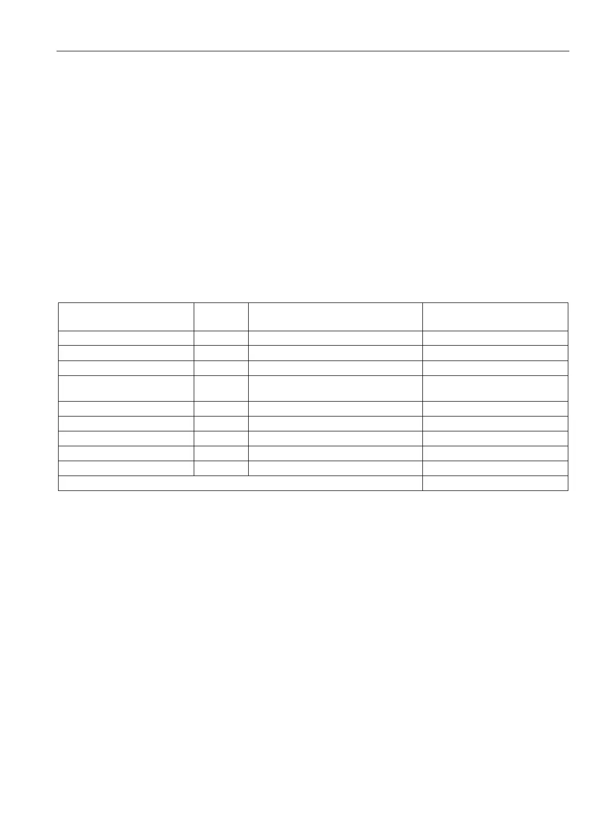
Table 12- 17 Example, calculating the power loss of a drive configuration
Total power loss [W]
(including electronic losses)
Line filter 1 16 16
S120 Combi 3 axes Power
Module 20 kW
1 634 634
A
ssumption:
free-standing control cabinet surface A = 5 m
2
difference between the room temperature and the temperature inside the control cabinet ∆T
= 10 K
q = 1146.8 W - 5.5 W / (m
2
K) * 5 m
2
* 10 K = 871.8 W

 Loading...


