Cabinet design and EMC
12.6 24 V DC supply
SINAMICS S120 Combi
Manual, (GH9), 07/2016, 6SL3097-4AV00-0BP5
295
24 V power supply and connection of components
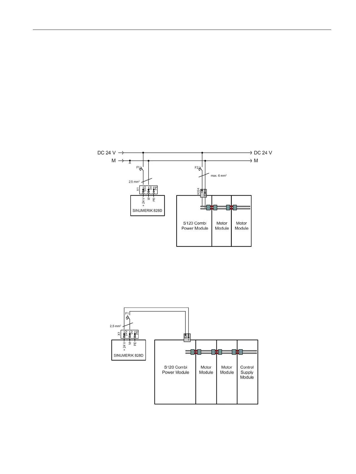
The S120 Combi with the expansion axes (Motor Modules) and DC link components are
connected to the 24 V DC via the integrated 24 V busbars. The current carrying capacity of
these busbars is 20 A.
The power can be supplied in two ways:
1. When using an external 24 V power supply, e.g. SITOP, the 24 V connector must
be
us
ed. The external power supply should be located very close to the load (max. cabl
e
l
ength 10 m). Miniature circuit breakers with tripping characteristic D are recommended
as overcurrent. The ground potential M must be connected to the protective conductor
system (DVC A).
Figure 12-1 Example of an external 24 V power supply
2. When a Control Supply Module is used, the 24 V supply can be directly established
through the busbars. The electronic current limiting function integrated in the Control
Supply Module protects the busbar system when a fault occurs. Additional loads can be
connected via the 24 V connector.
Figure 12-2 Example of a 24 V supply with Control Supply Module

 Loading...


