Setup
3.1 Punching and nibbling tools
3-37
SINUMERIK 802D sl Operation and Programming Nibbling (BP-N), 06/2006 Edition
6FC5 398-3CP10-0BA0
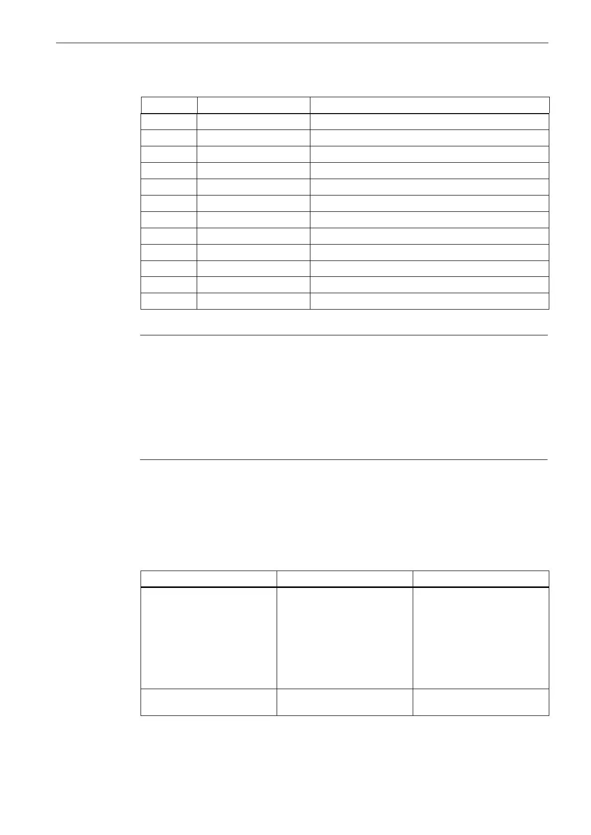
Table 3-2 Parameter list for nibbling, continued
Parameters DescriptionField
DP25 Sheet thickness Current sheet thickness
DPC1 Axis of the driven tool Tool orientation can be changed by way of rotary axis
DPC2 Location Tool location
DPC3 Maximum sheet thickness Maximum sheet thickness
DPC4 No. of the multi-tool Number of the toolholder
DPC5 DPC5 Free
DPC6 DPC6 Free
DPC7 DPC7 Free
DPC8 DPC8 Free
DPC9 DPC9 Free
DPC10 DPC10 Free
Important
The meanings of the DP2, DP6, DP12 and DP24 parameters is defined in conjunction with
part program simulation as follows:
S DP2 Reserved for part program simulation
S DP6 Tool geometry
S DP12 Angle of tool orientation
S DP24 Envelope diameter
and cannot be overwritten.
Interrelation between geometry data and cutting edge parameters
The geometry data required for the simulation of punching/nibbling tools can be mapped to
the cutting edge parameters as follows:
Table 3-3 Interrelation ’geometry data – cutting edge parameters’
Geometry
Tool geometry Cutting edge parameters
Round,
hexagon or octagon,
triangle,
double “D”,
single “D”,
long “D”,
rectangle,
square,
elongated hole
Envelope diameter
Orientation angle
DP24
DP12
Rectangle, square Y Length of the tool edge
X Length of the tool edge
DP8
DP9

 Loading...


