Configuration
5-34 7SJ62 Manual
C53000-G1140-C121-1
Configuration
Sheet
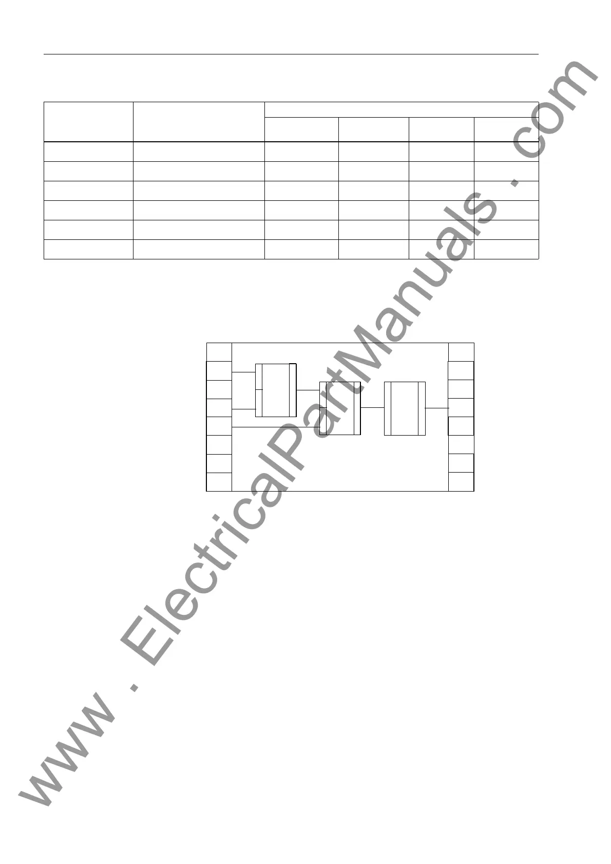
The configuration is performed within the configuration sheets (see Figure 5-33).
Figure 5-33 Principal Representation of Function Modules in a DIGSI
®
4 Working Page
The left border column of the configuration sheet shows the inputs; the right border
column shows the outputs of a function. In the above diagram the inputs are connect-
ed with input signals IS1 to IS3. These may be indications from the breaker (via binary
inputs), from relay function keys, or from a protective function. The output signal (OS4
in the diagram) may control an output relay, for example, and can create entries in the
message buffers, depending on the preset configuration.
Configuring and
Connecting Func-
tion Modules
The default run-time sequence is determined by the sequence of the insertion of the
logic modules. You may redefine the run-time sequence by pressing Ctrl – F11 on the
PC keyboard. Please refer to the CFC manual. The necessary function modules (FM)
are contained in a library located to the right of the configuration chart. The module
also indicates to which of the four task levels (MW_BEARB, PLC1_BEARB,
PLC_BEARB, SFS_BEARB) it is assigned. The modules possess at least one input
and one output. In addition to these inputs and outputs, which are displayed on the
configuration sheet, a module may have additional inputs. The additional inputs can
be made visible by selecting the module title block, pressing the
right
mouse button,
selecting the menu option1XPEHU2I,2V (see Figure 5-34), and then increas-
ing the number.
RS_FF RS-Flipflop –XXX
SR_FF SR-Flipflop – X X X
TIMER Timer – X X –
UPPER_SETPOINT Upper limit X – – –
X_OR XOR-Gate – X X X
ZERO_POINT Zero suppression X – – –
Table 5-5 Selection Guide for Function Modules and Task Levels
Function Modules Description
Task Level
MW_BEARB
Meter processing
PLC1_BEARB
Slow PLC
PLC_BEARB
Fast PLC
SFS_BEARB
Interlocking
IS1
IS2
IS3
OS4
FM2
1
2
3
FM1
1
2
3
FM3
1
2
Configuration Sheet 1
Input
Signals
Output
Signals
Function Modules
www . ElectricalPartManuals . com

 Loading...


